



Note: This describes the removal for a gasoline engine. Since not all model variants can be considered, before removing the cylinder head, you should check again whether all the wires and other connections from the head and to the head are loose. Features that concern the diesel engine are described at the end.
Remove the cylinder head only when the engine is cold (at room temperature). Do not remove the outlet and partially also the inlet pipes.
A defective cylinder head gasket is determined by one or more of the following signs:
- Loss of power.
- Loss of coolant. White exhaust gases when the engine is warm.
- Loss of oil.
- The presence of coolant in the engine oil, the oil level does not decrease, but it becomes less. Gray color of engine oil, foam emulsion on the oil level indicator, the oil is liquid.
- Engine oil in coolant.
- The coolant is bubbling violently.
- There is no compression in two adjacent cylinders.
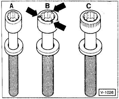
Attention: From 3/95 on engines with the designation AEK, AAM, ADZ, ADY (ABF s 2/ 94), a metal cylinder head gasket and modified cylinder head bolts are installed. The metal gasket can also be installed on earlier engines (ABS, 2E), but in this case, modified "B" bolts are required first. These bolts can be identified by the projections (arrows) on the heads. The ABF engine cylinder head bolts have been modified: "C". The letter "A" denotes the previously used bolts with a smooth head.
Removal
Disconnect the battery ground (-) cable.
Drain the coolant, see chapter "Cooling system".
Remove the air filter, see chapter "Power supply system".
Unscrew the generator support at the cylinder head.
Disconnect the coolant hoses from the cylinder head and intake manifold.
Disconnect the gas rod, do not remove the plug retainer.
Note: Most electrical plug connectors are made with metal clamps. Before disconnecting, depending on the design, the clamps must be pressed or compressed, thereby releasing the connector from the lock.
Carburetor engines
Disconnect the vacuum hoses from the intake manifold and carburetor. To facilitate subsequent assembly, mark the hoses with tags.
Disconnect the fuel supply line from the carburetor and plug it with a suitable plug.
Disconnect the plug connectors of the intake manifold heating system and the fuel shut-off valve. Loosen the wire clamp at the cylinder head cover.
Remove the electrical wires and vacuum hose from the distributor valve at the carburetor.
Engines with injection systems?
Mono-Jetronic system: Unscrew the fuel supply and return lines from the combined injection system and seal the openings with suitable plugs. Remove all electrical wires and the vacuum hose from the ignition distributor. Remove the central injection system, see chapter "Petrol injection system".
Digifant and K-Jetronic systems: unscrew the fuel manifold from the cylinder head and remove the valve injectors from the cylinder head, see chapter "Petrol injection system".
Unscrew the exhaust pipe from the exhaust pipe, see chapter "Exhaust system".
Loosen the timing belt and remove it from the top of the camshaft, see above.
Mark the electrical wires from the hydraulic switch and temperature sensor and remove.
Remove the spark plug caps.
Disconnect the vacuum hose from the carburetor to the ignition distributor.
To facilitate subsequent assembly, mark the position of the bracket at the cylinder head cover and unscrew it together with the cover. Remove the oil deflector, see above.
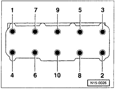
Loosen the cylinder head cover bolts with a key with external slots (for example, HAZET990 Slg-12). The bolts must first be loosened by 1/2 turn in the specified sequence, and then completely unscrewed in the same sequence.
Check that all wires and hoses leading to the cylinder head are disconnected.
Remove the cylinder head and place it on two wooden blocks.
Remove the cylinder head gasket
Installation
Before installation, clean the cylinder head and cylinder block from seal residues using a suitable scraper. Make sure that dirt does not get into the cylinder block holes. Cover the holes with rags.
Check for oil in the cylinder head bolt holes. If necessary, insert a clean rag into the holes and collect the oil.
Caution: If oil remains in the holes, the engine block may be damaged when tightening the bolts.
Check the cylinder head for deflection using a steel ruler.
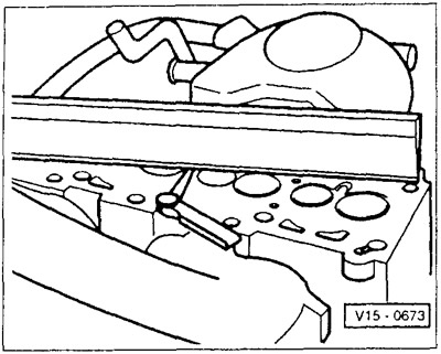
Check the deflection using a steel ruler and feeler gauge in various places on the cylinder head. The maximum permissible unevenness should not exceed 0.1 mm. (For a 16-valve engine, the unevenness should not exceed 0.05 mm). The cylinder head of a diesel engine must not be flat ground.
Attention: If the contact surfaces of the cylinder head of a gasoline engine are subject to finishing, the permissible height of the finished head must not be less than a = 132.6 mm.
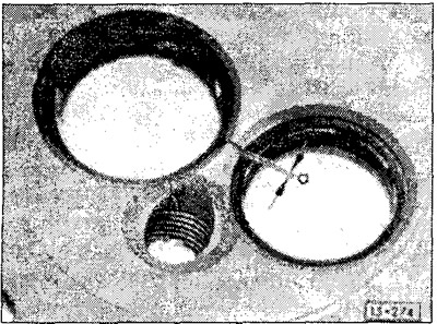
Cylinder heads with cracks in the intervalve bridge and the first thread turns under the spark plugs may not require repair and may continue to be used if the maximum width of the cracks does not exceed a = 0.5 mm.
The cylinder head gasket must be replaced.
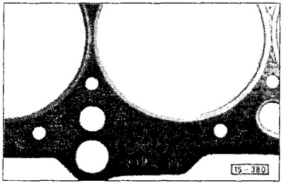
The "oben" (top) marking on the sealing gasket must face the cylinder head. The cylinder head sealing gasket must be laid dry and on a dry surface so that the openings in the cylinder block are not covered. For a diesel engine, ensure that the sealing gasket is of the required thickness.
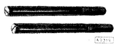
To center the cylinder head, prepare guide pins, which can be two old cylinder head bolts with heads cut off and slots cut for a screwdriver.
Screw the guide pins into holes 8 and 10.
Install the cylinder head.
Insert bolts with washers into the remaining 8 holes and tighten them by hand. The cylinder head bolts must be replaced. Depending on the type of sealing gasket being installed, use the appropriate cylinder head bolts, see above.
Use a screwdriver to unscrew the guide pins, insert the 2 remaining bolts with washers and tighten them by hand.
Caution: Cylinder head bolts must be tightened very carefully. The torque wrench must be checked for accuracy before tightening. Cylinder head bolts must be tightened on a cold engine.
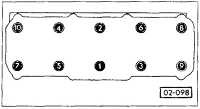
The cylinder head bolts are tightened in 4 stages. In each stage, the bolts are tightened in sequence from 1 to 10. The values given below are valid for all 4-cylinder engines:
- Method 1: using a torque wrench with a torque of 40 Nm.
- Method 2: using a torque wrench with a torque of 60 Nm.
- Step 3: Without stopping tightening, turn in the tightening direction by 1/4 turn (90°) using the locked key.
- Step 4: Without stopping tightening, turn in the tightening direction by 1/4 turn (90°) using the locked key.
When tightening the cylinder head bolts, evaluate the angle of rotation of the wrench. Place the wrench handle along the cylinder head and turn it in one stroke to a position perpendicular to the axis of the head (1/4 turn is 90°).
Caution: On diesel engines manufactured before 9/93, tighten the cylinder head bolts when warm. Tightening the cylinder head bolts on warm petrol engines and diesel engines manufactured since 10/93 is not permitted as part of maintenance or repair.
(The original text is available on the portal: www.VWmanual.ru)
Install the timing belt, see above.
Caution: When installing another cylinder head with a camshaft installed instead of the old head, lubricate the contact surfaces of the plate tappets and cams after installing the cylinder head.
Install the cylinder head cover with oil deflector with new seals and tighten to 10 Nm. For a carburetor engine, install the fuel settling chamber bracket together with the cylinder head cover.
Install the timing belt cover, see above.
Install the generator support.
Engine with injection system: Install the injection system, see chapter "Petrol injection system".
Carburetor engine: connect the plug connectors of the intake manifold heating system and the fuel shut-off valve. Secure the wire clamp to the cylinder head cover.
Connect the electrical wires to the carburetor or injection system.
Connect the vacuum hoses to the intake manifold and carburetor as marked. Secure the hoses with clamps if necessary.
Attach the gas rod.
Connect the fuel supply line to the carburetor and secure it with a clamp.
Connect the distributor vacuum hose to the carburetor or MoPo-Jetronic system.
Connect all coolant hoses and secure them with clamps.
Connect the electrical wires to the temperature sensor, put on the spark plug tips.
Install the air filter, see chapter "Power supply system".
Check the engine oil level. If the cylinder head gasket is defective, replace the oil.
Warm up the engine to normal operating temperature, check the coolant level, and check all hose connections for leaks.
Check the ignition timing, see chapter "Ignition system".
Check idle speed adjustment, see chapters "Power supply system" and "Petrol injection system".
Removal a diesel engine
Disconnect the electrical wires from the connectors and glow plugs.
Clean the fuel lines between the high-pressure fuel pump and the injectors with a cleaning agent and unscrew. Close the holes with appropriate caps.
Remove the glow plugs and injectors, see chapter "Diesel engine".
Installation
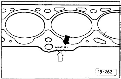
Depending on the piston protrusion above the cylinder block surface, sealing gaskets of different thicknesses are installed. When replacing a gasket, pay attention to the designation. Install a new gasket only with the same designation. The black arrow points to the location of the spare part number; white arrow - to the designation (holes or teeth), if it is present on the gasket being installed.
Diesel engines manufactured before 9/93: Tighten the cylinder head bolts when the engine is warm. To do this, warm up the engine and let it idle until the radiator fan comes on (oil temperature above +50°C). Without first loosening and without interrupting the tightening, tighten the cylinder head bolts an additional 1/4 turn (90°) in the tightening direction using the locked wrench. Pay attention to the tightening sequence, see Figure 02-098.
Note: Since 10/93, a metal cylinder head gasket has been installed as standard. Therefore, tightening the cylinder head bolts on a warm engine with this gasket is no longer necessary.
Install glow plugs, see chapter "Diesel engine".
Install the injectors, see chapter "Diesel engine".
Clean the high-pressure fuel line connections with a cleaning agent. Tighten the union nuts to a torque of 25 Nm.
Connect the electrical wires to the fuel switch and glow plugs.
Check the start of injection of the high-pressure fuel pump, see chapter "Diesel engine".
1.6L turbocharged diesel engine (rA/SB designation): After repairs and a mileage of approximately 1000 km, the cylinder head bolts must be tightened. Without first loosening and without interrupting the tightening, tighten the cylinder head bolts by 1/4 turn (90°) in the tightening direction using the locked wrench. Pay attention to the tightening sequence, see Figure 02-098. The bolts can be tightened with a cold or warm engine.
Visitor comments