



Removing
After installation, it is necessary to reinstall all cable fasteners that are removed or cut off during dismantling.
Remove engine covers.
Remove ignition coils with output stages.
Remove the hose between the G70 air mass meter and the throttle control module.
Disconnect the 6-pin connector from the throttle valve control module J338 and the 2-pin connector from the N80 activated charcoal filter solenoid valve 1 and the crankcase breather valve.
Disconnect the vacuum hoses 1-3 from the intake manifold. On vehicles with engine code BAA and BMX, additionally remove vacuum hose 4 from the intake manifold.
Unscrew the fixing bolt 5 of the intake manifold support (pic. 2.56).
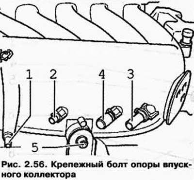
Then unscrew the fastening of the intake manifold on the left and right side of the manifold.
Disconnect the crankcase ventilation hose from the cylinder head cover.
Unscrew fixing bolts 1 and 2 on the intake manifold (pic. 2.57).
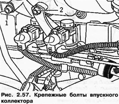
Disconnect the vacuum hose from the intake manifold vacuum switch actuator.
Unbolt the intake manifold from the cylinder head.
Remove the intake manifold and place it on a clean surface so as not to damage the vacuum drive element.
NOTE: The intake ports in the intake manifold and in the block head should be covered with a clean rag.
Unscrew the holder for wires to knock sensor 1 G61 and oil level and temperature sensor G266 from the front on the cylinder head cover.
Remove the cylinder head cover.
Installation
Installation is carried out in the reverse order, taking into account the following features.
The intake manifold must first be bolted to the cylinder head.
Then tighten both heat shield bolts and intake manifold support bolts.
Check fuel hoses for tightness.
Tightening torques
| Threaded connection | Tightening torque, Nm |
| Cylinder head cover to cylinder head | 10 |
| intake manifold to cylinder head | 13 |
| intake manifold to support | 20 |
| Heat shield to exhaust manifold | 23 |
| Oil dipstick tube to intake manifold | 8 |
Visitor comments