
Diesel engine 5.0 liter car Volkswagen Touareg 1

5.0L Diesel Engine Specifications
Table 2.4 Engine code AYH BKW* BLE BWF Date of manufacture 10.02 12.03-10.04 11.04 02.06 Complies with toxicity regulations EU3 Tier1 EU4/Tier2** - Working volume, l 4,9 4,9 4,9...
Table 2.4 Engine code AYH BKW* BLE BWF Date of manufacture 10.02 12.03-10.04 11.04 02.06 Complies with toxicity regulations EU3 Tier1 EU4/Tier2** - Working volume, l 4,9 4,9 4,9...
5.0L Diesel Engine Mounting Torques
Threaded connection Tightening torque, Nm Engine to gearbox M10 45 (without starter) M12 80 Engine support to cylinder block 50 Engine mount to engine mount 75 Engine mount to...
Threaded connection Tightening torque, Nm Engine to gearbox M10 45 (without starter) M12 80 Engine support to cylinder block 50 Engine mount to engine mount 75 Engine mount to...

Removing the engine
NOTE: The engine is removed with the gearbox down. Before dismantling, interrogate the fault memory of all control units. NOTE: To ensure unobstructed rotation of the driveshaft,...
NOTE: The engine is removed with the gearbox down. Before dismantling, interrogate the fault memory of all control units. NOTE: To ensure unobstructed rotation of the driveshaft,...

Removal and installation of pillows and support of the engine
Removing Remove the front soundproofing. Remove the lower part of the air filter of the first and second row, cylinder air filter. Unscrew the engine mounting nuts on the left and...
Removing Remove the front soundproofing. Remove the lower part of the air filter of the first and second row, cylinder air filter. Unscrew the engine mounting nuts on the left and...

Crushing and installing the driven disk
Fix the VW 558 clutch counterholder with an M8x50 hexagon bolt on the driven disk (pic. 2.166). Install three M12 hex nuts between the counter support and the driven disc....
Fix the VW 558 clutch counterholder with an M8x50 hexagon bolt on the driven disk (pic. 2.166). Install three M12 hex nuts between the counter support and the driven disc....
Removal and installation of the crankshaft support ramp
NOTE: Removal of the balance shaft is only possible if the transfer case module has been previously removed. WARNING: The upper part of the engine mount rail is connected to the...
NOTE: Removal of the balance shaft is only possible if the transfer case module has been previously removed. WARNING: The upper part of the engine mount rail is connected to the...

Front flange seal and vibration damper
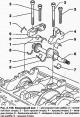
Pic. 2.172. Front flange seal and vibration damper: 1 - front gasket of the flange; 2 - bolt 8 Nm; 3 - water pump cover; 4 - torsional vibration damper; 5 - bolt 50 Nm + tighten...
Pic. 2.172. Front flange seal and vibration damper: 1 - front gasket of the flange; 2 - bolt 8 Nm; 3 - water pump cover; 4 - torsional vibration damper; 5 - bolt 50 Nm + tighten...

Replacing the crankshaft seal on the vibration damper side
Work order Bring the radiator frame to the service position. Remove the vibration damper. NOTE: When dismantling the gland, make sure that the seating surface is not damaged....
Work order Bring the radiator frame to the service position. Remove the vibration damper. NOTE: When dismantling the gland, make sure that the seating surface is not damaged....

Replacing the crankshaft oil seal on the timing side of the engine
Work order NOTE: When dismantling the gland, make sure that the seating surface is not damaged. Carefully remove the old O-ring using a puller T20143/2 (pic. 2.177). Wipe off any...
Work order NOTE: When dismantling the gland, make sure that the seating surface is not damaged. Carefully remove the old O-ring using a puller T20143/2 (pic. 2.177). Wipe off any...

Replacement of an epiploon of a shaft of a drive of the generator
Vehicles with engine codes AYH, BKW Remove the fuel filter. Vehicles with BLE and BWF engines Remove the bypass cover with the recirculation cooler. Assembly operations for all...
Vehicles with engine codes AYH, BKW Remove the fuel filter. Vehicles with BLE and BWF engines Remove the bypass cover with the recirculation cooler. Assembly operations for all...

Timing cover installation
Pic. 2.182. Timing cover: 1 - dispensing mechanism module; 2 - cover of the distribution mechanism; 3 - bolt 20 Nm; 4 - bolt 20 Nm; 5 - sealing ring; 6 - driven disk; 7 - bolt 50...
Pic. 2.182. Timing cover: 1 - dispensing mechanism module; 2 - cover of the distribution mechanism; 3 - bolt 20 Nm; 4 - bolt 20 Nm; 5 - sealing ring; 6 - driven disk; 7 - bolt 50...

Removal and installation of the camshaft drive gear
NOTE: After each removal of the gear train during assembly, it is necessary to check and, if necessary, adjust the position of the pistons of the unit injectors. NOTE: The...
NOTE: After each removal of the gear train during assembly, it is necessary to check and, if necessary, adjust the position of the pistons of the unit injectors. NOTE: The...

Checking the valve timing
Work order Remove the soundproofing and casings from the cylinder heads. Rotate the crankshaft with counter support T10172 slowly in the direction of rotation of the engine shaft...
Work order Remove the soundproofing and casings from the cylinder heads. Rotate the crankshaft with counter support T10172 slowly in the direction of rotation of the engine shaft...

Valve timing adjustment
Work order Remove the engine and gearbox. Remove the fuel pump and tandem pump from the cylinder heads. Remove the soundproofing and casings from the cylinder heads. Remove a...
Work order Remove the engine and gearbox. Remove the fuel pump and tandem pump from the cylinder heads. Remove the soundproofing and casings from the cylinder heads. Remove a...

Removal and installation of heads of the block of cylinders
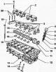
Pic. 2.201. Cylinder head components: 1 - connecting hose (in vehicles with BLE and BWF engines); 2 - sealing cuff (in vehicles with BLE and BWF engines); 3 - holder (in vehicles...
Pic. 2.201. Cylinder head components: 1 - connecting hose (in vehicles with BLE and BWF engines); 2 - sealing cuff (in vehicles with BLE and BWF engines); 3 - holder (in vehicles...

Removal and installation of covers and linings of heads of the block of cylinders
Follow the tightening sequence of the cylinder head cover fixing bolts (pic. 2.205). Tighten the fixing bolts in the sequence shown to 10 Nm. Cylinder head gasket marking NOTE:...
Follow the tightening sequence of the cylinder head cover fixing bolts (pic. 2.205). Tighten the fixing bolts in the sequence shown to 10 Nm. Cylinder head gasket marking NOTE:...
Repair of cylinder heads
Pic. 2.207. Valve train components: 1 - bolt 20 Nm + tighten 1/4 turn. (90°); 2 - axis of roller levers; 3 - bearing cap; 4 - poppet pusher; 5 - conical cracker; 6 - valve spring...
Pic. 2.207. Valve train components: 1 - bolt 20 Nm + tighten 1/4 turn. (90°); 2 - axis of roller levers; 3 - bearing cap; 4 - poppet pusher; 5 - conical cracker; 6 - valve spring...

Valve seat processing
NOTE: When repairing engines with leaky valves, it is not sufficient to remake or replace the valve seats and valves. Especially in engines with a long service life, the valve...
NOTE: When repairing engines with leaky valves, it is not sufficient to remake or replace the valve seats and valves. Especially in engines with a long service life, the valve...

Checking the valve guides
Insert the new valve into the guide sleeve. The end of the valve stem must be covered by the guide bushing. Due to the different stem diameter, use the inlet valve in the inlet...
Insert the new valve into the guide sleeve. The end of the valve stem must be covered by the guide bushing. Due to the different stem diameter, use the inlet valve in the inlet...

Replacing valve stem seals
NOTE: With cylinder head installed. Remove the camshaft. Remove the poppet lifters and lay them with the working surface down. Do not swap poppet pushers. Move the piston of the...
NOTE: With cylinder head installed. Remove the camshaft. Remove the poppet lifters and lay them with the working surface down. Do not swap poppet pushers. Move the piston of the...

Checking the pressurization system for leaks
Remove the air intake hose 1 from the air filter. Insert the adapter 1687/10 into the air intake sleeve 1 and secure it with a clamp. Prepare the VAG 1687 boost tester for testing...
Remove the air intake hose 1 from the air filter. Insert the adapter 1687/10 into the air intake sleeve 1 and secure it with a clamp. Prepare the VAG 1687 boost tester for testing...

Installation of hose connections with nipple connectors
WARNING: The o-ring of the nipple connector may be damaged if the retaining clip is in the locked position during installation. As a result, leakage occurs. Follow the...
WARNING: The o-ring of the nipple connector may be damaged if the retaining clip is in the locked position during installation. As a result, leakage occurs. Follow the...
Turbocharger check
ATTENTION: If mechanical defects are found on the turbocharger, such as a defective impeller, it is not enough to just replace the turbocharger. To avoid the appearance of...
ATTENTION: If mechanical defects are found on the turbocharger, such as a defective impeller, it is not enough to just replace the turbocharger. To avoid the appearance of...
This section is available on russian, bulgarian, belarusian, ukrainian, serbian, croatian, romanian, polish, slovak, hungarian
Touareg 1
- General information
- Vehicle device
- Controls and instruments
- Seats and safety
- Maintenance and management
- Power unit
- Engine checks
- Petrol engine 3.2L
- Petrol engine 4.2L
- Diesel engine 5.0L
- Cooling system
- Lubrication system
- Injection system
- Exhaust system
- Fuel supply system
- Transmission
- Automatic gearbox 09D
- Mechanical gearbox 08D
- Cardan shaft
- Chassis
- Wheels and tires
- Front suspension
- Rear suspension
- Steering gear
- Brake system
- Body
- Outdoor elements
- Electrical equipment
- Battery
- Generator and starter
- Instruments and wipers
VWmanual.ru © 2016-2024 | Mobile version | News and articles | Sitemap: EN BG BY UA RS HR RO PL SK HU | Write message | Site search
Passat B2 • Passat B3 • Passat B4 • Passat B5 • Passat B6 • Golf 1, diesel • Golf 1, petrol • Golf 2, petrol • Golf 2 • Golf 3 • Golf 4 • Golf 5 • Polo 3 • Polo 4 • Touareg 1 • Tiguan 1 • Sharan 1 • Transporter T3 • Transporter T4 • Beetle • Caddy 3 •
Passat B2 • Passat B3 • Passat B4 • Passat B5 • Passat B6 • Golf 1, diesel • Golf 1, petrol • Golf 2, petrol • Golf 2 • Golf 3 • Golf 4 • Golf 5 • Polo 3 • Polo 4 • Touareg 1 • Tiguan 1 • Sharan 1 • Transporter T3 • Transporter T4 • Beetle • Caddy 3 •