
NOTE: After each removal of the gear train during assembly, it is necessary to check and, if necessary, adjust the position of the pistons of the unit injectors.
NOTE: The workflow described below and the components shown are for the first row cylinders. The differences from the second row of cylinders are minor and do not require a description.
Removing
Remove the engine and gearbox.
Remove the intake manifold flap and crankcase ventilation hose resp. cylinder.
Remove the soundproof cover and cylinder head cover of the corresponding block head.
Check the running surfaces of the swing arm axle for signs of wear or damage.
Disconnect the water pipe under the tandem and fuel pump.
Remove the vibration damper.
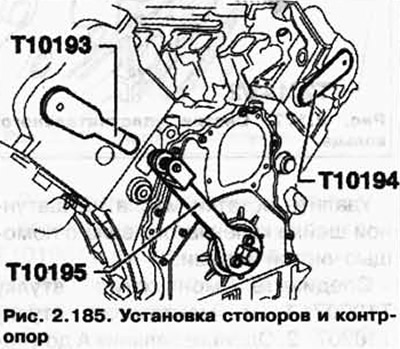
Use counterhold T10172 with screws T10172/1.
Screw the T10195 crankshaft stopper to the end of the crankshaft. When doing this, pay attention to the position of the dowel pin.
After that, carefully rotate the crankshaft until the protrusion of the crankshaft stop T10195 falls into the calibration holes (pic. 2.185).
Remove the respective pump.
1st row of cylinders: tandem pump.
2nd row of cylinders: fuel pump.
Disconnect the oil supply line to the turbocharger.
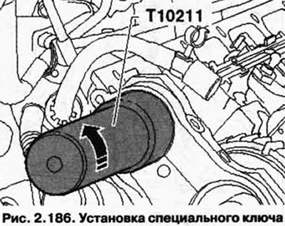
Insert the key T10211, as shown in Figure 2.186, and loosen the adapter ring of the central connector of the unit injectors.
Remove Hall sensor G40-C (only for 1st row of cylinders).
Dismantle the outer cover of support A, install the jig T10199 on the camshaft gear and tighten the bolts of the device from 40 Nm.
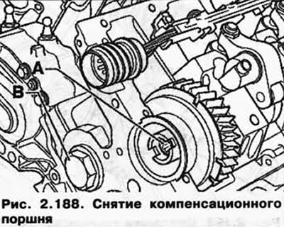
Loosen the fixing bolt B of the camshaft gears using the T10198 end socket and unscrew together with the tandem pump drive mechanism (pic. 2.187).

Loosen the T10199 jig bolts and remove it.
Unscrew the compensation piston In the removable axis of the compensation lining (pic. 2.188).
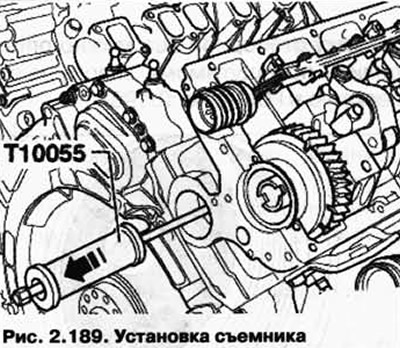
Unscrew the removable head of the pump-injector from the T10055 puller.
Screw the puller T10055 as shown in Figure 2.189 into the guide axle, gently tapping, remove the axle in the direction of the arrow.
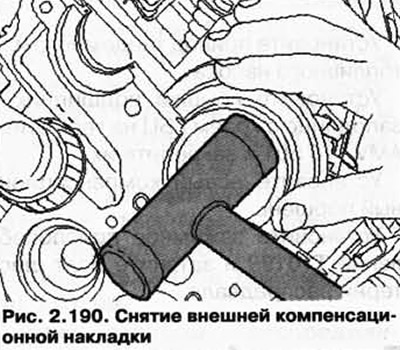
Remove the outer (on the checkpoint side) compensation pad from its socket. If necessary, knock it off with light blows of a plastic hammer (pic. 2.190).
Remove the camshaft gear.
Now remove the compensation gear and the internal compensation pad.
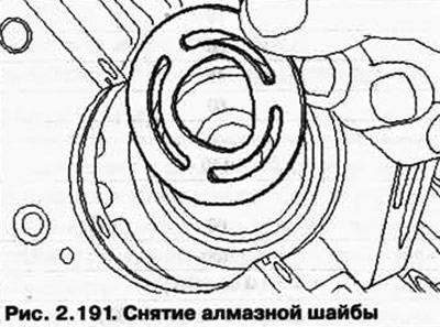
Remove the diamond washer from the camshaft console (pic. 2.191).
Installation
Clean the contact surfaces of the bearing caps from sealant residues.
Lubricate the guide surfaces of the bushing of the compensation pad with oil.
NOTE: If there is noticeable wear or deposits on the guide surface of the bushings of the wear pads, they must be replaced without fail.
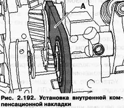
Hook on the inside (on the engine side) wear pad A at the bottom first (if necessary, guide a finger through the hole in the balancing piston) and finally slide on top of the sleeve (pic. 2.192).
Install a new diamond washer on the camshaft console.
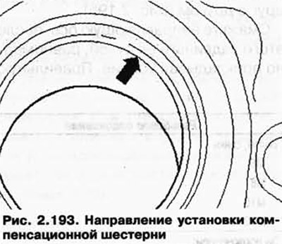
Bring bottom wear pad (on the checkpoint side) into position and set the compensation gear in phase (pic. 2.193) towards the checkpoint.
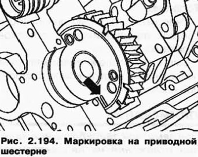
When installing, turn the camshaft gear so that the marking (pic. 2.194) on the drive gear coincided with the upper edge of the seating surface.
Secure the knot by carefully inserting (as evenly as possible) locking axle by hand.
WARNING: There is a risk that the lining of the gear cluster may slip to the side and not fit on the steering axle, or misalignment will occur when the axle is pushed in.
Insert the guide bush into the wear pad on the gearbox side.
Carefully remove the locking pin. When doing this, make sure that the compensation pads that have already been adjusted remain in the correct position.
Install the compensation pad on the side of the gearbox with the inscription to the gearbox. If necessary, support it with light blows of a plastic hammer on the guide bush.
Check that the wear pads are seated correctly with your finger through the bore of the offset piston.
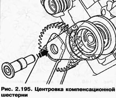
The compensation gear must be centered so that the holes on the four linings and on the gear coincide with each other (pic. 2.195).
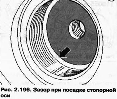
Lubricate the guide axle, then slide it in by hand, applying even pressure. The correct fit of the locking axle can be determined by a noticeable gap to the hole in the cylinder head (pic. 2.196).
Install the tandem or fuel pump drive.
Install the bearing caps flush with the edge of the cylinder head using sealant AMV 176 501 and secure them.
Install a new compensation piston.
Install jig T10199 and tighten the camshaft gear bolt.
Tightening torques
| Threaded connection | Tightening torque, Nm |
| Bolts, nuts | |
| M6 | 10 |
| M8 | 20 |
| M10 | 45 |
| M12 | 60 |
| With the exception of: | |
| compensation piston | 110 |
| Camshaft Gear Bolt | |
| Stage 1 | 60 |
| Stage 2 | 150 |
| EtalZ | 1/4 vol. (180°) |
| Support cover bolt | 8 + tighten 1/4 turn. (90°) |
Visitor comments