
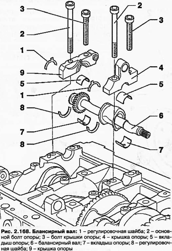
NOTE: Removal of the balance shaft is only possible if the transfer case module has been previously removed.
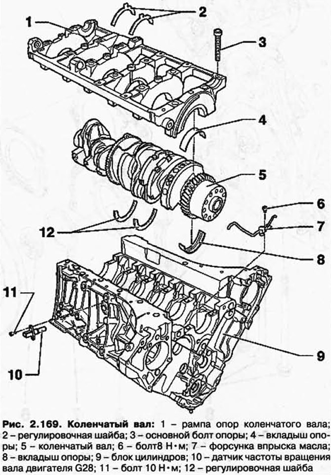
WARNING: The upper part of the engine mount rail is connected to the cylinder block by means of two M8 hexagon socket bolts located between the cylinder heads. Under no circumstances should these connections be untwisted, as the result is an irreparable deformation of the cylinder block.
NOTE: The engine must be secured with the IMS 6095 engine and gearbox fixture for installation work.
Establish clamping device T10201 on the lower part of the crankshaft support ramp as shown in Figure 2.170.
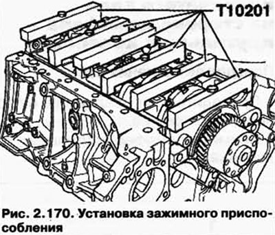
Tighten the T10201 jig bolts to 20 Nm.
Remove the bottom of the engine mount ramp.
Installation
Install jig T10201 on the bottom of the crankshaft support ramp and tighten the bolts to 20 Nm.
Make sure that all bearing bushings are properly seated in the bearing brackets.
Pay attention to adjusting washers.
Carefully install the bottom of the crankshaft support rail into the cylinder block.
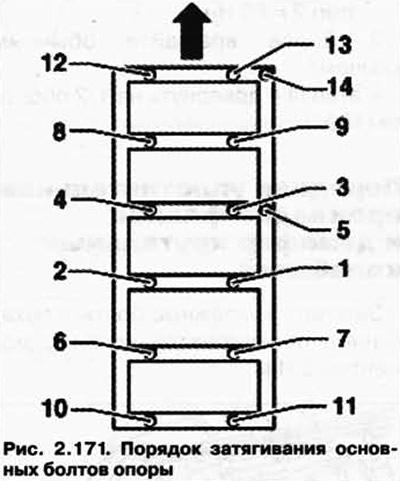
Tighten the main support bolts in three stages in the sequence shown (pic. 2.171) shows the direction of travel).
1 - Tighten with a torque wrench:
- stage 1 = 35 Nm;
- stage 2 = 65 Nm.
2 - Next, rotate with a regular key:
- step III = tighten 1/2 turn (180°).
Visitor comments