
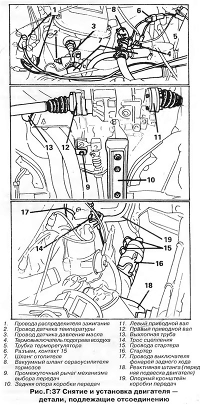
Withdrawal (pic. D:37)
The engine is removed from the car up assembled with the transmission, then separated from it. It is not necessary to remove the hood, but this significantly increases the working space.
1. Disconnect the wires from the battery and remove the battery.
2. On carbureted engines, remove the air filter along with the hoses; close the inlets (diffusers) carburetor to prevent dirt from entering.
3. If the windshield washer reservoir is located in the front right corner of the engine compartment, remove the reservoir together with the pump from the holder and place it in the cavity in front of the windshield.
4. On vehicles with dual headlights, remove the covers from the headlights.
5. Drain the liquid from the cooling system by disconnecting the lower radiator hose from the cooling pump housing, and collect it in a clean container - the heater tap must be open (see chapter "Cooling system").
6. On models equipped with an oil cooler, remove the oil cooler located on the right side of the main radiator and place it on top of the engine. Do not disconnect the oil cooler hoses.
7. Remove the radiator assembly with shroud and radiator fan.
8. Disconnect the wires from the following nodes by marking the cables and connectors with adhesive tags:
- A) Distributor (high and low voltage wires).
- b) coolant temperature sensor (on the left side of the cylinder head)
- V) Oil pressure sensor (above the temperature sensor).
- G) Carburetor Inlet Heater Thermal Switch (in the presence of).
- d) TDC sensor (on early models, at the top of the clutch housing).
- e) Generator.
- and) Reversing light switch (top of the clutch housing).
- h) Starter (solenoid relay).
9. Disconnect hoses of system of cooling from branch pipes on a head and the block of cylinders.
10. Disconnect the brake booster vacuum hose from the intake manifold.
11. On models with a carbureted engine, remove (disconnect) the following details:
- A) The fuel line coming from the fuel tank is from the fuel pump.
- b) Fuel return line - from carburetor or from tee (models before 1979).
- V) Throttle cable - from carburetor and bracket (do not remove the cable clamp (in the presence of).
- G) On models with automatic transmission: Throttle cable mounting bracket on carburetor or cylinder head. Do not change cable adjustment.
- d) Vacuum reservoir. Put the tank on the engine.
12. On models with a fuel injection system, disconnect or remove the parts listed below (pic. D:38). Mark all hoses, cables and wires to facilitate their subsequent installation.
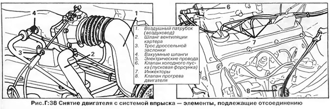
- A) Air connection (duct) between the throttle body at the intake manifold and the air mass sensor at the fuel rail.
- b) Crankcase ventilation hose from the tee on the valve cover.
- V) Accelerator cable from brackets on the valve cover and throttle body.
- G) Vacuum hoses from the nozzles on the intake manifold.
- d) Cold Start Valve Harness Connector (starting nozzle) on the right side of the intake manifold and the starter injector from the manifold.
- e) Head injectors (do not disconnect the fuel pipes from the injectors. Install protective caps on them).
- and) The connector of the wires of the engine warm-up regulator from the cylinder block.
- h) Connector wires from the thermal switch on the coolant outlet pipe on the cylinder head.
- And) Fuel distributor with air filter. Place the knot aside without disconnecting anything from it.
- To) Pipe branch (duct) air intake with air filter. Separate the bottom of the air filter.
13. Disconnect the speedometer drive cable from the top of the gearbox housing and plug the hole in the gearbox.
14. On models with a manual transmission, disconnect the clutch cable from the transmission.
15. On manual transmission models, disconnect the gear selector top and tie rods from the transmission. Loosen the top nut securing the intermediate lever to the steering gear housing.
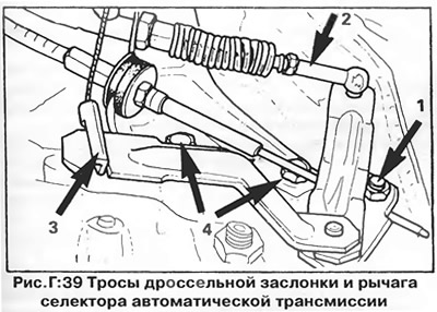
16. On models with automatic transmission, set the selector lever to the position "R". Disconnect the selector lever cable (1) from the bracket and lever on the transmission (pic. D:39). Disconnect the throttle cable (2) from the bracket, then disconnect the accelerator pedal cable (3). Unscrew the bracket (4) from the transmission case.
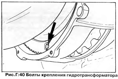
17. On models with automatic transmission, remove the bolts securing the torque converter to the drive plate (pic. D:40).
18. On models with a manual transmission, unscrew the bottom nut and remove the intermediate lever along with the transverse link of the gear selector mechanism.
19. Turn out a stopper from the pallet crankcase and merge engine oil in the substituted container; close the stopper.
20. Disconnect the rear support bracket from the gearbox housing and body.
21. Disconnect the drive shafts from the transmission and hang them to the body on wire hooks.
22. Disconnect a reception pipe of the muffler from a final collector. (If the exhaust pipes are attached to the engine and gearbox with brackets, remove the brackets).
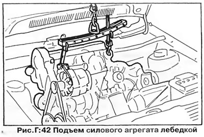
23. Attach the engine to a lifting device and raise it slightly to take the load off the supports (see chapter "Basic rules for work").
24. Remove the starter, then remove the torque rod (front suspension) engine.
25. Disconnect the engine support bracket from the body side member on the right side of the vehicle (pic. D:41).
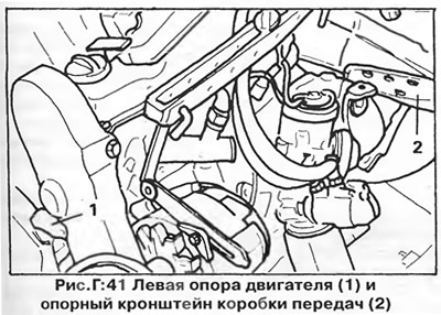
26. Disconnect the gearbox support bracket from the gearbox housing and body (left).
27. Slightly rotate the engine and transmission and carefully lift the unit out of the engine compartment, guiding it so as not to damage the body.
ATTENTION: On vehicles with a 1V3 carburetor with a vacuum air damper unloader, be especially careful not to touch the protruding parts of the carburetor behind the body.
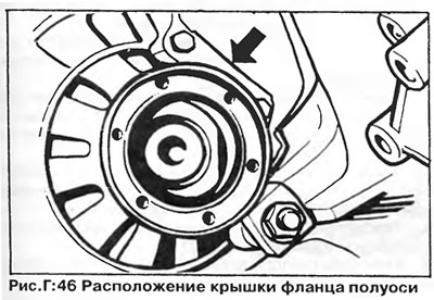
28. Separate the transmission from the engine (having previously removed the cover of the right flange of the axle shaft - fig. D:46).
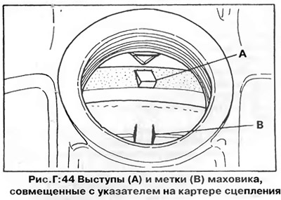
29. On cars with a manual transmission, manufactured before November 1978, in order to remove the gearbox from the engine, it is necessary to set the flywheel to a certain position. To do this, turn the engine crankshaft so that one of the three projections (B, fig. D:44) or labels (Ah, fig. D:44) on the flywheel is aligned with the TDC indicator on the clutch housing (pic. D:44). These marks should not be confused with the 0-shaped TDC mark. The gearbox has a locating pin, so it must move away from the engine strictly along the axis of the crankshaft, and if the flywheel is not set to the desired position, then the flange of the right axle shaft will not be able to pass the flywheel. On later vehicles, the locating pin has been replaced with a bolt and nut, and it is not necessary to install the flywheel in this way, since the gearbox can be rotated when removed. On injection models, the flange of the right axle shaft has a cutout, which should be turned towards the flywheel.
Engine installation
The engine is installed in the reverse order of removal. Pay attention to the following:
- A) On early production vehicles with cutouts on the flywheel, before connecting the gearbox to the engine, one of the cutouts must be aligned with the flange of the right axle shaft - see chapter "Clutch and manual transmission".
- b) Be careful when lowering the engine with transmission into the engine compartment so as not to damage the unit and drive shafts.
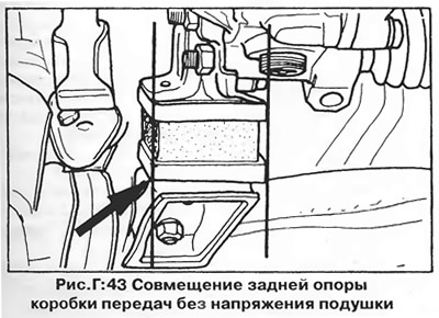
- V) Attach the left support bracket to the transmission first. Then attach the engine and gearbox mounts to the body without tightening the bolts, then level the unit and tighten the mounting bolts. The rear support must be aligned so that the rubber pad is not under undue stress (pic. D:43).
- G) Tighten the engine-to-gearbox mounting bolts to the torque specified in section "Technical data".
- d) Position the exhaust system so that it does not experience excessive stress; if necessary, bend the hooks to which the system is attached.
- e) Adjust the accelerator cable as described in chapter "Fuel system".
- and) Adjust the clutch cable so that the pedal free play is as specified in section "Technical data".
- h) Fill the oil pan with the recommended grade of oil in the required quantity - see section "Technical data".
Visitor comments