



Contents: Replacing the camshaft seal ↓ Removal the camshaft ↓ Installing the camshaft ↓ Identification of camshafts ↓
Replacing the camshaft seal
The camshaft seal is replaced without removing the shaft from the cylinder head.
1. Remove the timing belt as described previously. Loosen and remove the camshaft sprocket bolt, remove the sprocket and woodruff key.
2. Remove the old oil seal from its seat in the cylinder head using a special puller (figure G:10) or carefully pull it out with a screwdriver/wire hook.
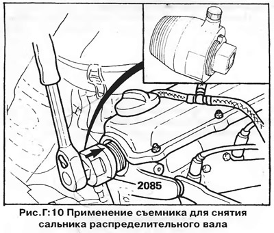
3. Make sure that the oil seal seat in the cylinder head is not damaged and is clean. Lubricate the working edge and the outer edge of the new oil seal with engine oil.
4. Insert the seal into the hole and, using a special tool, (figure G:12) press it in so that it is flush with the cylinder head. You can use a socket wrench of the appropriate diameter as a mandrel. Install the seal evenly, without skewing.
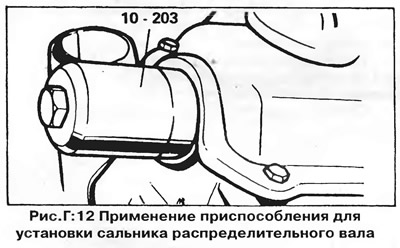
CAUTION: Do not press the seal all the way in, as this will close the oil return channel.
5. Reinstall the previously removed parts. Adjust the tension of the toothed belt and the alternator belt as described earlier.
Removal the camshaft
1. Remove the valve cover. Note the location of the vacuum hoses that are disconnected. On some models, the air filter must be removed to gain access to the cylinder head.
2. Set the crankshaft to the TDC position of the compression stroke of the 1st cylinder, then remove the toothed belt and related parts as described earlier.
3. Remove the camshaft sprocket and woodruff key.
4. Remove the middle and two outer camshaft bearing caps (i.e. bearing caps No.1, 3, and 5 - Figure D:13). Gradually, in a diagonal sequence, loosen the nuts securing the two remaining caps (No. 2 and 4), then remove the caps. Lay the caps out in order and note their position relative to the cylinder head, since the caps can only be installed in one position.
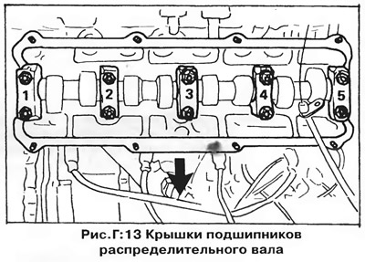
CAUTION: The camshaft oil seal installed in bearing #1 will be displaced when the cover is removed. A new oil seal must be installed when installing the shaft.
5. Remove the camshaft, being careful not to lose the adjusting shims located on top of each tappet.
Installing the camshaft
1. Align the timing marks on the crankshaft pulley and the auxiliary shaft sprocket (figure G:6), while the ignition distributor rotor must be aligned with the cylinder No.1 mark on the housing.
2. If the lower timing belt cover is installed (on models with two timing belt covers), then it is impossible to see the timing mark on the auxiliary shaft sprocket. In this case, make sure that the TDC mark on the flywheel or drive disk is aligned with the pointer in the inspection hole in the clutch housing (figure G:44).
3. Install the camshaft in the cylinder head so that the cams of cylinder No.1 are facing upward.
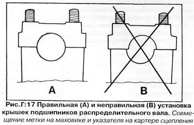
4. Install the camshaft bearing caps. Make sure that the caps are installed in the only correct position (figure G:17). Tighten the bearing cap nuts #2 and #4 evenly and in a diagonal sequence (figure G:13) with a torque of 2.0 kg·m. Then tighten the nuts of the remaining bearing caps (No. 1, 2 and 3). Before tightening the fastening of cover E, install it finally in place by lightly tapping on the end of the camshaft.
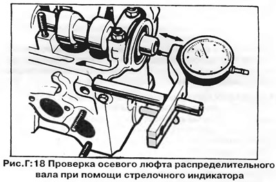
5. Check the axial play of the camshaft using a dial indicator (figure G:18). The axial clearance should not exceed 0.15 mm. Check the axial clearance by installing only bearing caps No.1 and No.5 and removing the valve tappets.
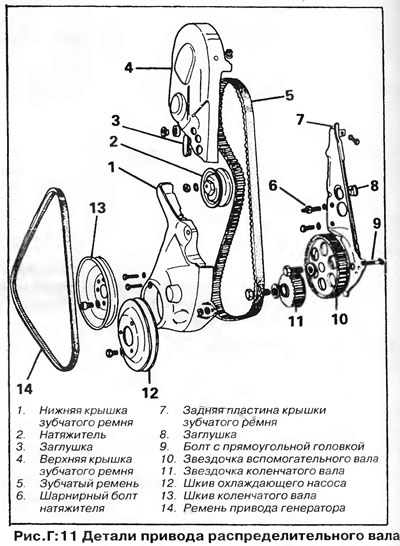
Install the new camshaft seal into the bearing bore #1 as described previously. Install the remaining parts removed earlier. Figure G:11 shows the camshaft drive components.
Identification of camshafts
Depending on the engine type and date of manufacture, the camshaft may be one of several modifications. Different camshafts have different camshaft shapes and heights and provide different valve timing.
The camshaft of early 1.5 L (1471 cc) engines has a cast ring on the first cam (A, figure G:14).
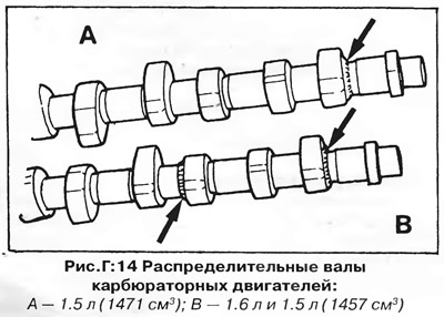
The camshaft of the 1.6 L (1588 cc) and later 1.5 L (1457 cc) engines has cast rings on the first and third cams (B, figure G:14). The same camshaft was installed on early injection engines (A, figure G:15).
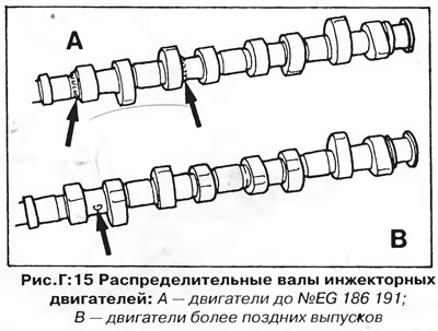
Since December 1979, injection engines have been equipped with a camshaft with modified valve timing, designated by the letter "G" between the cams of the 1st cylinder (B, figure G:15).
When replacing the camshaft, make sure you purchase a new shaft of the correct modification.
Some cylinder heads are supplied as spare parts with camshafts that have undersized journals. These shafts are installed with bearing shells and can be identified by the yellow spot on the VW/Audi logo.
Visitor comments