
Cylinder head bolts
There are two types of cylinder head bolts (pic. D:19).
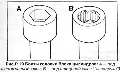
Both types of bolts have an M11 thread and differ in the shape of the wrench socket. Initially, 10 mm hex bolts were installed, then they were replaced with spline bolts ("star") size 12 mm. When repairing, it is recommended to replace the old bolts with new ones.
To loosen the bolts, you will need either a hex or 12-point slot wrench (see section "Tool and equipment").
Bolts are tightened in two stages with the required torque (see section "Technical data"), then tighten by turning another 1/2 turn. In the future, when carrying out maintenance, it is impossible to tighten the cylinder head bolts.
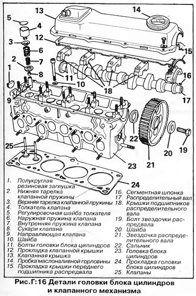
Removing the cylinder head (pic. D:16)
1. Disconnect the wire "masses" from the battery.
2. Disconnect the bottom hose from the radiator from the coolant pump housing and drain the coolant into a clean container. When draining the fluid, the heater tap must be open.
3. On models with carbureted engines, remove the air filter along with related hoses. Close diffuser openings (inlet pipe) carburetor to prevent dirt and small parts from entering the engine.
4. Disconnect wires of gauges of temperature and pressure of oil from the back party of a head of the block of cylinders. Label the wires with tags for easy reassembly.
5. Remove wires from spark plugs, having marked them with numbers of corresponding cylinders.
6. Disconnect the cooling system hoses from the cylinder head and intake manifold.
7. Disconnect the brake booster vacuum hose from the intake manifold.
8. On carbureted engines, disconnect or remove the following parts:
- A) Fuel supply pipe from the carburetor.
- b) Fuel return pipe from carburetor or tee (models up to 1979.
- V) Throttle cable from carburetor and bracket (do not remove the cable sheath fastening clip (in the presence of)).
- G) On models with automatic transmission, the throttle cable mounting bracket on the carburetor or cylinder head (do not change the cable adjustment).
- d) The vacuum tube of the ignition distributor from the carburetor.
- e) Wires from the automatic choke, solenoid shut-off valve and intake manifold heater (in the presence of).
9. On models with a fuel injection system, disconnect or remove the following items, marking them if necessary for ease of reassembly (see fig. D:38):
- A) Air connection (duct) between the throttle body on the intake manifold and the air mass sensor at the fuel rail.
- b) Crankcase ventilation hose at the tee on the valve cover.
- V) Accelerator cable from brackets on the valve cover and throttle body.
- G) Vacuum hoses from the nozzles on the intake manifold.
- d) Connector wires from the idle start valve (starting injector) and a cold start valve from the intake manifold.
- e) Head injectors (see chapter "Fuel system") - Do not disconnect fuel lines. Install the protective caps on the injectors.
- and) Wires from the thermal switch at the water outlet on the cylinder head.
10. Disconnect a reception pipe of the muffler from a final collector.
11. Remove the alternator drive belt, coolant pump pulley, toothed belt cover and toothed belt as previously described.
12. Remove the valve cover along with the gasket from the cylinder head.
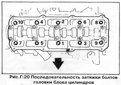
13. With a special key (see "Cylinder head bolts") uniformly loosen the cylinder head bolts in the reverse order shown in fig. G:20.
14. Remove the cylinder head and gasket. Be sure to install a new gasket when assembling.
Installing the cylinder head
Installation is carried out in the reverse order of removal. Pay attention to the following:
- A) If hex head bolts have been installed, they must be replaced with new spline bolts ("star" - see section "Cylinder head bolts").
- b) Clear interfaced surfaces of a head and the block of cylinders. When removing the remnants of the old gasket, be careful not to damage the cylinder head.
- V) If the cylinder head was removed to replace a blown gasket, check the head mating surface for warping and unevenness using a ruler and feeler gauges. The non-flatness of the surface should not exceed 0.1 mm. If the height of the irregularities is greater, the surface of the head can be restored by machining, but after processing, the height of the head should not be less than 132.6 mm. If the cylinder head height is less than 132.6 mm, replace the head.
- G) Install a new head gasket, check that it is in the correct position, and that the channels in the cylinder block line up with the gasket holes. The gasket must be installed with the side marked with the part number facing up.
- d) Insert bolts 8 and 10 (pic. D:20), to align the head to the cylinder block exactly, but do not overtighten them.
- e) Insert the rest of the bolts. Evenly, in several stages, tighten the cylinder head bolts in the sequence shown in fig. D:20 with the moment specified in the section "Technical data". The slotted head bolts do not need to be tightened further after the engine has been started.
- and) Reinstall the toothed belt and all other parts.
Disassembly of the cylinder head
1. Remove intake manifold with carburetor (or throttle body on fuel injected models) assembled.
2. Remove the exhaust manifold.
3. Remove the spark plugs.
4. Remove the water outlet pipes together with the coolant temperature sensor from the end, as well as from the side of the cylinder head.
5. Remove the covers of the 1st, 3rd and 5th camshaft bearings (rice. D:13). Evenly, in a diagonal sequence, loosen the fastening nuts on the two remaining covers (#2 and #4) and remove covers. Arrange the covers in order and mark their position on the cylinder head as the bearing bores are offset and the covers can only be installed in one position. Remove the camshaft.
6. Remove the valve lifters together with the shims from the slots in the head. Lay out the pushers and washers in the same order in which they were installed in order to install them in their original places during assembly.
7. Remove carbon deposits from combustion chambers and valve heads with a wooden or plastic scraper. Be careful not to damage the soft aluminum alloy cylinder head. Remove carbon from the piston heads and cylinder block as well, leaving a narrow ring of carbon around the top edge of each cylinder and around the piston. Use a jet of compressed air to remove carbon deposits from the cylinder head and block, after plugging all channels for oil and coolant with a rag.
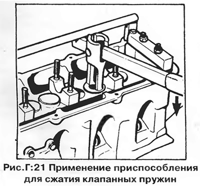
8 Due to their design, the valve springs are recessed in the cylinder head casting and require a special tool to compress them (pic. D:21). If there is no such device, you can independently make an adapter for a conventional universal valve spring puller. As an adapter, a piece of pipe with a diameter of 25 mm is used with windows cut on both sides, through which, after compression of the spring, valve crackers can be removed.
9. On each valve in turn:
- A) Compress the valve spring with tool (pic. D:21).
- b) Remove the two cone cotters fitted around the top end of the valve stem, then loosen and remove the spring compressor.
- V) Remove the top plate and valve spring.
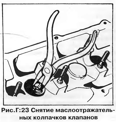
- G) Remove the slinger cap from the valve stem as shown in fig. G:23. The illustration shows the tool VW N910-218, but you can use a pair "platypuses".
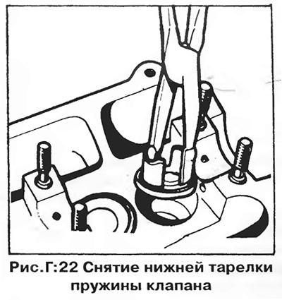
- d) Remove the lower spring plate using the same tool or "platypuses" (pic. D:22).
- e) Remove the valve from the cylinder head and mark its position on the head.
10. Clear all details of a head of the block of cylinders. Remove all remnants of old gaskets.
Inspection and repair of the cylinder head
Inspect valves, valve seats, guides and springs as described in chapter "Engine 1.0/1.3".
NOTE: Repair valves are supplied as spares and are 0.5mm shorter than standard valves. These valves are used for regrinding seats where the correct clearance cannot be obtained with a standard length valve.
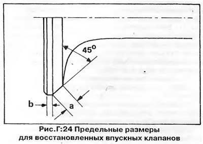
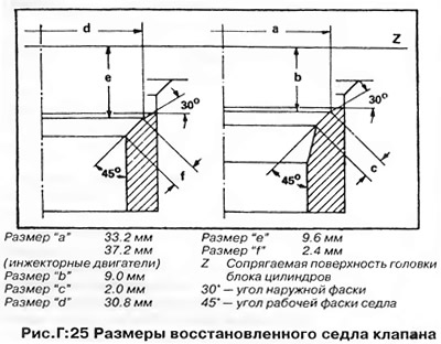
Exhaust valves with significant defects should not be machined - they should be replaced if manual lapping does not give satisfactory results. Inlet valves as well as valve seats can be machined (polished) on a special machine. The limiting dimensions for regrinding intake valves are shown in fig. D:24, and for regrinding valve seats - in fig. G:25.
Cylinder head assembly
Assemble the cylinder head in the reverse order of its dismantling. Pay attention to the following:
1. Lappe each valve to the seat first with a coarse then fine lapping paste until a continuous dull gray ring is obtained on the seat and valve facets. Carefully remove any remaining lapping paste from the cylinder head and valves.
2. Be sure to replace the valve stem seals When inserting new seals over the ends of the valve stems, be careful not to damage the seals on the sharp edges of the stems.
3. When installing the valves, make sure that the conical cotters fit correctly into the groove of the stem and into the seat of the upper spring plate.
4. Make sure that the pushers and their shims are installed in their original locations.
5. Place the camshaft in the bearings. Install bearing caps #2 and #4) camshafts, making sure they are correctly positioned (rice. D:17). Tighten the nuts of the covers evenly, in a diagonal sequence, with a torque of 2.0 kgm. Install the three remaining covers.
6. Check the axial play of the camshaft using a dial indicator (rice. D:18). The play should not exceed 0.15 mm. When checking for play, only bearing caps #1 and #5 should be installed, and the valve tappets should be removed.
7. Install a new camshaft oil seal as shown in rice. D:12. Press the seal up to the level of the surface of the cylinder head.
8. Adjust valve clearances on a cold engine as previously described. Check the clearances at normal engine operating temperature after approximately 1000 km.
9. When installing the valve cover, make sure that the semi-circular rubber plug is correctly positioned at the rear end of the camshaft.
10. When installing parts (intake and exhaust manifolds, water outlet, etc.) always use new gaskets.
Visitor comments