



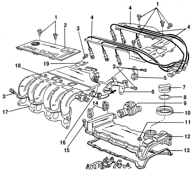
Pic. 26. Details of the upper part of the cylinder head: 1 - bolts (5 Nm); 2 - central cover (above the top of the intake manifold); 3 - bolts (25 Nm); 4 - spark plug wire holders; 5 - throttle cable holder; 6 - rear left bracket of the upper part of the inlet pipeline; 7 - filler cap for oil filling; 8 - sealing gasket; 9 - crankcase ventilation valve; 10 - ring in the cylinder head cover; 11 - nut (10 Nm); 12 - cylinder head cover; 13 - sealing gasket of the cylinder head cover; 14 - holders of fuel lines; 15 - bolt (10 Nm); 16 - vacuum hose; 17 - sealing gasket of the upper part of the intake manifold; 18 - the upper part of the intake manifold; 19 - rear right bracket of the upper part of the intake manifold
The parts that need to be removed in order to dismantle the cylinder head from the cylinder block are shown in fig. 26.
The cylinder head is removed from the engine on the vehicle unless the entire engine needs to be disassembled to fix the problem. Remove the cylinder head in the following order:
- disconnect the terminal «–» from AB;
- remove the upper part of the air filter;
- disconnect the plug connectors of the throttle switch, heating element, mass air flow sensor and intake air temperature sensor;
- remove the crankcase vent valve 9 (pic. 26) from the cylinder head cover 12;
- Disconnect the vacuum hose 16 of the activated carbon system from the top of the intake manifold 18. At the same time, make sure that the hose does not touch other parts;
- remove the air hose with the mass air flow sensor from the throttle body;
- remove high voltage wires (VN) with spark plugs;
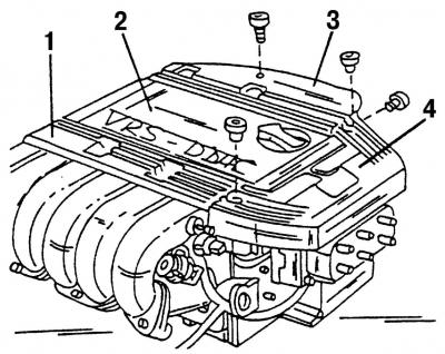
Pic. 27. The upper part of the intake manifold: 1, 3, 4 - high voltage wire guides; 2 - central cover
- remove guides 1, 3, and 4 (pic. 27) HV wires and unscrew bolts 1 shown in fig. 26, and remove the center cover 2 of the upper part of the intake manifold;
- remove the throttle cable together with its support, for which unscrew the support and remove the end of the cable. Do not pull out the clamp holding the throttle cable in the support, as this will require adjustment of the throttle cable tension;
- open the cap of the expansion tank of the cooling system to remove any excess pressure and drain the coolant;
- mark the cooling system hoses attached to the throttle body and remove them from the fittings;
- disconnect the vacuum hose of the inlet valve for the secondary air supply system;
- Disconnect the brake booster vacuum hose from the intake manifold. The location of this connection is 16 (pic. 26);
- remove the fuel lines (supply and removal of fuel) from holders 14 on the cylinder head and carefully disconnect the fuel hoses. Wrap a thick cloth around the connection before removing the hoses, as the fuel system is under pressure;
- unscrew the oil dipstick guide tube located at the bottom of the intake manifold;
- unscrew the mounting bolts and remove the rear left 6 (pic. 26) and right 19 brackets between the top of the intake manifold and the cylinder head;
- remove the upper part of the intake manifold 18 together with the throttle body. Make sure that the relief sleeves do not pop out. The inlets are now open, so close them in an appropriate way, for example by plugging them with clean rags;
- unscrew the fastening bolts 15 and remove the cylinder head cover 12 together with the gasket 13;
- on the side of the cylinder head cover, disconnect the electrical cable holder and the EGR valve (exhaust gas recirculation valve);
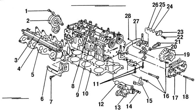
Pic. 28. Partially disassembled cylinder head (parts located on the top of the head were removed): 1 - bolt, 25 Nm; 2 - belt tensioner; 3 - fuel supply distributor; 4 - sealing gasket of the lower part of the intake manifold; 5 - the lower part of the intake manifold; 6 - lifting eye; 7 - bolt, 25 Nm; 8 - a bolt of fastening of a head of the block of cylinders; 9 - cylinder head; 10 - cylinder head gasket; 11 - bolt, 25 Nm; 12 - O-shaped sealing ring; 13 - thermostat housing; 14 - bolt, 10 Nm; 15 - cable holder; 16 - bolt, 10 Nm; 17 - ignition coil; 18 - bolts, 10 Nm; 19 - holder; 20 - sealing ring; 21 - chain tensioner, 30 Nm; 22 - bolt, 10 Nm; 23 - Hall sensor; 24 - spacer ring; 25 - O-ring; 26 - spacer ring; 27 - camshaft cover; 28 - O-ring
- then unscrew holder 19 (pic. 28), which fixes the plug with 42 contacts, as well as an additional pump of the cooling system, designed to protect the stopped engine from overheating;
- Disconnect the plug connector of the coolant temperature sensor;
- remove the V-belt for driving engine units;
- disconnect the front pipe with the catalyst from the exhaust manifold;
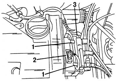
Pic. 29. Ignition coil location: 1 - wire fastening; 2 - plug block; 3 - fastening bolt
- unscrew the fastening bolts 3 (pic. 29) and disconnect the ignition coil 17 (rice 28) from the cylinder head;
- remove the steering gear (see subsection 12.1) so that the upper two-row chain of camshaft sprockets is released;
- unscrew the tensioner of the lower single-row chain of the intermediate shaft drive, located on the side of the cylinder head;
- remove the cover 27 camshafts. When installing, the cover must be covered with sealant (AMV188 001 002). If only the cylinder head cover was removed, and the cylinder block itself was not removed, then the cylinder head gasket should be prepared for installation of the cover in accordance with the recommendations given below;
- disconnect all electrical wires from the cylinder head;
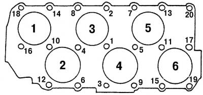
Pic. 30. The sequence of tightening the cylinder head bolts. Unscrewing the bolts is carried out in reverse order
- unscrew in several stages in the reverse order indicated on (pic. thirty), cylinder head bolts;
- remove the cylinder head. If it is stuck, then it can be hit several times with a plastic or rubber hammer to facilitate removal;
- if further disassembly of the cylinder head is necessary, then the lower part of the intake manifold, belt tensioner, fuel distributor and other parts mounted on the cylinder head should be removed.
Visitor comments