



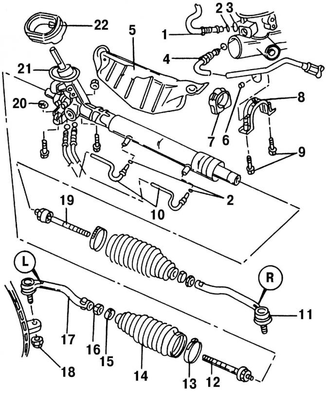
Pic. 262. Steering: 1 - recirculation hose; 2 - sealing ring; 3 - threaded connection of the recirculation hose; 4 - discharge pipeline, 30 Nm; 5 - thermal insulation screen; 6 - nut; 7 - rubber support; 8 - clamp with welded nuts; 9 - bolt, 60 Nm (replace always); 10 - pipeline; 11 - tie rod joint, right (R label); 12 - left tie rod, 70 N·m; 13 - collar; 14 - protective cover; 15 - clamp; 16 - nut, 55 Nm; 17 - tie rod joint, left (label L); 18 - self-locking nut, 30 Nm + 90°; 19 - right tie rod, 70 N·m; 20 - self-locking nut; 21 - power steering mechanism; 22 - rubber gasket
Steering gear removal procedure (pic. 262):
- disconnect the AB terminals, and completely remove it;
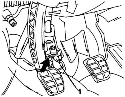
Pic. 263. After loosening bolt 1, tilt the panel (shown by arrow) to one side to disengage the steering joint connection
- from inside the car, disconnect the steering joint (pic. 263). To do this, loosen the bolt and remove the clamping rail;
- loosen the wheel bolts, put the front of the car on supports and remove the front wheels;
- remove the engine protection;
- remove the intake pipe from the exhaust manifold;
- unscrew the bolt on the outer side of the pendulum support;
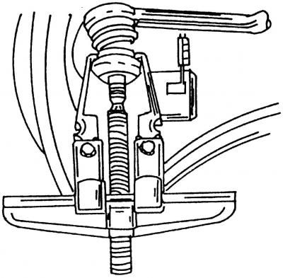
Pic. 264. Removing the ball joint of the tie rod
- unscrew the nuts of the bolts with a ball head from the steering trapezium rods and with a puller press the hinges of the rods from the levers (pic. 264);
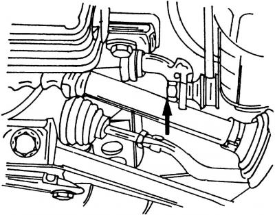
Pic. 265. Nut connecting rod on the anti-roll bar (shown by arrow)
- disconnect the anti-roll bar link (pic. 265);
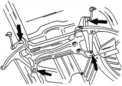
Pic. 266. Arrangement of bolts of fastening of a subframe. Bolt tightening torque 150 Nm + 90°
- install a jack under the subframe and remove it (pic. 266). Lower the jack, remove the mounting clamps and remove the steering gear towards the rear. Remove the heat shield;
- if necessary, remove the sealing collar from the steering gear.
- The installation of the steering mechanism is carried out in the reverse order of the removal process. Wherein:
- if it was removed, then reinstall the sealing cuff. With the steering gear installed, it should be located without deformation on the bottom from the passenger compartment;
- install the steering gear and mounting clamps. bolts (use only new) wrap in nuts welded to the clamps. Tightening torque - 60 Nm;
- slowly raise the subframe until it returns to the correct starting position. Tighten the bolts (pic. 266) specified tightening torque;
- connect the power steering hoses. Install new sealing rings in the joints;
- install the connecting rods on the anti-roll bar. Use only new nuts. Tightening torque - 100 N·m;
- connect the hinges of the steering trapezoid rods with the steering arms and tighten the nuts (use only new) a torque of 30 Nm, and then tighten them by another 90°;
- install the wheels, lower the car to the ground and tighten the wheel bolts to 140 Nm;
- set the steering to the position of driving the car in a straight line;
- from inside the vehicle, connect the steering rack to the clutch and install a new bolt. Bolt tightening torque 25 Nm (pic. 263);
- check the fluid level in the tank and top up if necessary;
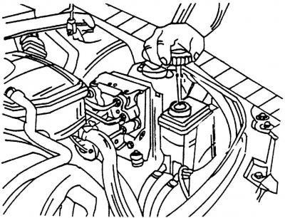
Pic. 267. Remove the cover of the power steering reservoir and check the level of hydraulic fluid with a dipstick (dipstick located on the cover)
- start the engine and watch the fluid level. The fluid level must not drop. If this happens, turn off the engine, disconnect the pressure pipe from the steering gear (its location is shown in Fig. 267) and wait until the liquid starts to flow out. After that, connect the pipeline and check the fluid level by starting the engine again;
- check the geometry of the front suspension and the position of the steering wheel.
Visitor comments