
Gasoline engine 2.8L (AAA) car Volkswagen Sharan 1

VR6 engine — design description
Pic. 15. Schematic representation of three types of six-cylinder engines used in the automotive industry: a - V-shaped 6-cylinder engine; b - VR6 engine; c - in-line engine This...
Pic. 15. Schematic representation of three types of six-cylinder engines used in the automotive industry: a - V-shaped 6-cylinder engine; b - VR6 engine; c - in-line engine This...

Removal and installation of the engine
The power unit consists of an engine and a gearbox. Remove it using a hydraulic lift or hoist, lowering it from the engine compartment. Before removing the power unit, do the...
The power unit consists of an engine and a gearbox. Remove it using a hydraulic lift or hoist, lowering it from the engine compartment. Before removing the power unit, do the...

Removal and installation of a transmission from the engine
Removing the gearbox from the engine (with power unit removed) run as follows: unscrew the bolts securing the gearbox to the engine; Together with an assistant, separate the...
Removing the gearbox from the engine (with power unit removed) run as follows: unscrew the bolts securing the gearbox to the engine; Together with an assistant, separate the...
Additional operations on an air-conditioned vehicle
Attention! Under no circumstances should the refrigeration circuit be opened, as skin contact with refrigerant may result in frostbite. This work can only be carried out by...
Attention! Under no circumstances should the refrigeration circuit be opened, as skin contact with refrigerant may result in frostbite. This work can only be carried out by...

Engine Mount
When replacing the engine mount, use fig. 23-25. It is necessary to jack up the engine in order to unload the individual suspension elements. Always observe the tightening torques...
When replacing the engine mount, use fig. 23-25. It is necessary to jack up the engine in order to unload the individual suspension elements. Always observe the tightening torques...
General recommendations for disassembly and assembly of the engine
Thoroughly wash the outside of the engine before starting disassembly. When disassembling, mark the location of removable parts and parts in order to reassemble them in their...
Thoroughly wash the outside of the engine before starting disassembly. When disassembling, mark the location of removable parts and parts in order to reassemble them in their...

Removing the cylinder head
Pic. 26. Details of the upper part of the cylinder head: 1 - bolts (5 Nm); 2 - central cover (above the top of the intake manifold); 3 - bolts (25 Nm); 4 - spark plug wire...
Pic. 26. Details of the upper part of the cylinder head: 1 - bolts (5 Nm); 2 - central cover (above the top of the intake manifold); 3 - bolts (25 Nm); 4 - spark plug wire...

Dismantling of a head of the block of cylinders
Disassemble the cylinder head in the following order: Pic. 28. Partially disassembled cylinder head (parts located on the top of the head were removed): 1 - bolt, 25 Nm; 2 - belt...
Disassemble the cylinder head in the following order: Pic. 28. Partially disassembled cylinder head (parts located on the top of the head were removed): 1 - bolt, 25 Nm; 2 - belt...

Cylinder head repair
Valve springs and valve guides To fully inspect the valve springs, a special spring test tool should be used. If not, then install the springs in a row on a smooth surface so that...
Valve springs and valve guides To fully inspect the valve springs, a special spring test tool should be used. If not, then install the springs in a row on a smooth surface so that...

Cylinder head assembly
Assemble the cylinder head in the reverse order of disassembly, observing the following recommendations: generously lubricate the valve stems with engine oil and insert them into...
Assemble the cylinder head in the reverse order of disassembly, observing the following recommendations: generously lubricate the valve stems with engine oil and insert them into...

Installing the cylinder head
Lay the cylinder head gasket in such a way that the inscription is visible from above «Oben» or «Top». Always install a new gasket; for the correct positioning of the gasket in...
Lay the cylinder head gasket in such a way that the inscription is visible from above «Oben» or «Top». Always install a new gasket; for the correct positioning of the gasket in...

Hydraulic pusher — removal and installation
Observe the following recommendations: after removal, hydraulic tappets should be installed with the contact surface down on a clean surface; always replace the pushers...
Observe the following recommendations: after removal, hydraulic tappets should be installed with the contact surface down on a clean surface; always replace the pushers...

Removing pistons and connecting rods
Pistons and connecting rods are knocked out of the cylinder block in an upward direction with a hammer handle, after removing the covers and shells of the connecting rod bearings....
Pistons and connecting rods are knocked out of the cylinder block in an upward direction with a hammer handle, after removing the covers and shells of the connecting rod bearings....
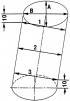
Measuring the inner diameter of a cylinder
Pic. 60. Scheme for measuring the inner diameter of the cylinder: 1, 2 and 3 - upper, middle and lower zones of the cylinder; A, B - transverse and longitudinal directions of...
Pic. 60. Scheme for measuring the inner diameter of the cylinder: 1, 2 and 3 - upper, middle and lower zones of the cylinder; A, B - transverse and longitudinal directions of...

Checking pistons and connecting rods
Clean the piston from carbon deposits and remove all deposits from the lubrication channels of the piston and connecting rod. Carefully inspect all details. Cracks of any nature...
Clean the piston from carbon deposits and remove all deposits from the lubrication channels of the piston and connecting rod. Carefully inspect all details. Cracks of any nature...

Assembly of pistons and connecting rods
To properly assemble the connecting rod with the piston and install it in the engine in the proper position, use the previously applied markings. If pistons have been replaced,...
To properly assemble the connecting rod with the piston and install it in the engine in the proper position, use the previously applied markings. If pistons have been replaced,...
Installation of pistons and connecting rods
Install pistons and connecting rods in the following order: generously lubricate the inner surfaces of the cylinders with engine oil; Pic. 63. Details of the piston group: 1 -...
Install pistons and connecting rods in the following order: generously lubricate the inner surfaces of the cylinders with engine oil; Pic. 63. Details of the piston group: 1 -...

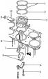
Cylinder block — check
Pic. 69. Cylinder block with parts installed on it: 1 - bolt, 25 Nm; 2 - pulley of the cooling pump; 3 - bolt, 20 Nm; 4 - pump of the cooling system; 5 - O-ring, always replace...
Pic. 69. Cylinder block with parts installed on it: 1 - bolt, 25 Nm; 2 - pulley of the cooling pump; 3 - bolt, 20 Nm; 4 - pump of the cooling system; 5 - O-ring, always replace...

Removing the crankshaft
To remove the crankshaft, remove the engine from the vehicle. Since the engine must be completely disassembled, follow these guidelines for completely disassembling the engine:...
To remove the crankshaft, remove the engine from the vehicle. Since the engine must be completely disassembled, follow these guidelines for completely disassembling the engine:...

Checking the crankshaft
Check the crankshaft by doing the following: inspect the crankshaft. Cracks anywhere on the crankshaft are not allowed. On surfaces mating with the working edges of the seals,...
Check the crankshaft by doing the following: inspect the crankshaft. Cracks anywhere on the crankshaft are not allowed. On surfaces mating with the working edges of the seals,...

Installing the crankshaft
The installation of the crankshaft should be carried out in the following order: Pic. 82. Elements of the crankshaft and main bearings: 1 - bearing cover bolt; 2 - main bearing...
The installation of the crankshaft should be carried out in the following order: Pic. 82. Elements of the crankshaft and main bearings: 1 - bearing cover bolt; 2 - main bearing...

Crankshaft seals
Pic. 85. Elements of the rear side of the engine: 1 - stuffing box cover; 2 - bolt, 25 Nm; 3 - bolt, 10 Nm; 4 - stuffing box; 5 - flywheel; 6 - flywheel mounting bolt; 7 - driven...
Pic. 85. Elements of the rear side of the engine: 1 - stuffing box cover; 2 - bolt, 25 Nm; 3 - bolt, 10 Nm; 4 - stuffing box; 5 - flywheel; 6 - flywheel mounting bolt; 7 - driven...
Flywheel — removal and installation
To remove the flywheel from the crankshaft, block it with a retainer in a stationary state and unscrew the flywheel mounting bolts, which can be immediately discarded, since only...
To remove the flywheel from the crankshaft, block it with a retainer in a stationary state and unscrew the flywheel mounting bolts, which can be immediately discarded, since only...

Timing mechanism drive — design description
Pic. 91. Elements of the timing mechanism drive: 1 - intermediate shaft; 2 - driving ring; 3 - bolt, 10 Nm; 4 - sensor drive; 5 - bolt, 10 Nm; 6 - bolt, 25 Nm; 7 - elastic element...
Pic. 91. Elements of the timing mechanism drive: 1 - intermediate shaft; 2 - driving ring; 3 - bolt, 10 Nm; 4 - sensor drive; 5 - bolt, 10 Nm; 6 - bolt, 25 Nm; 7 - elastic element...

Removal of details of a drive of the gas-distributing mechanism
Pic. 16. Camshaft drive of the VR6 engine Pic. 91. Elements of the timing mechanism drive: 1 - intermediate shaft; 2 - drive ring; 3 - bolt, 10 Nm; 4 - sensor drive; 5 - bolt, 10...
Pic. 16. Camshaft drive of the VR6 engine Pic. 91. Elements of the timing mechanism drive: 1 - intermediate shaft; 2 - drive ring; 3 - bolt, 10 Nm; 4 - sensor drive; 5 - bolt, 10...

Installing the timing drive
Pic. 92. Marking places for camshaft drive chains (shown by arrows) If the cylinder head is not removed, the timing chains are marked (pic. 92) and none of the camshafts has been...
Pic. 92. Marking places for camshaft drive chains (shown by arrows) If the cylinder head is not removed, the timing chains are marked (pic. 92) and none of the camshafts has been...

Intermediate shaft — removal and installation
Pic. 69. Cylinder block with parts installed on it: 1 - bolt, 25 Nm; 2 - pulley of the cooling pump; 3 - bolt, 20 Nm; 4 - pump of the cooling system; 5 - O-ring, always replace...
Pic. 69. Cylinder block with parts installed on it: 1 - bolt, 25 Nm; 2 - pulley of the cooling pump; 3 - bolt, 20 Nm; 4 - pump of the cooling system; 5 - O-ring, always replace...
Checking compression in the engine cylinders
To check if the valves are tight, if the piston rings are worn out, or if there are other malfunctions in the cylinders, measure the compression in the engine cylinders. To do...
To check if the valves are tight, if the piston rings are worn out, or if there are other malfunctions in the cylinders, measure the compression in the engine cylinders. To do...

Additional air supply system
This system pumps air past the exhaust valves for 65 seconds when the engine coolant temperature is between 15°and 35°C. As a result, oxygen-enriched exhaust gases exit the...
This system pumps air past the exhaust valves for 65 seconds when the engine coolant temperature is between 15°and 35°C. As a result, oxygen-enriched exhaust gases exit the...

Removal and installation of a final collector
Pic. 100. Elements of the front of the exhaust system: 1 - engine thermal protection screen; 2 - exhaust manifold, consisting of two parts; 3 - lifting eye; 4 - nut, 40 Nm; 5 -...
Pic. 100. Elements of the front of the exhaust system: 1 - engine thermal protection screen; 2 - exhaust manifold, consisting of two parts; 3 - lifting eye; 4 - nut, 40 Nm; 5 -...

Removal and installation of system of release of the fulfilled gases
The service life of the exhaust system as a whole depends on the conditions in which the vehicle is operated. With frequent trips over short distances, a significant amount of...
The service life of the exhaust system as a whole depends on the conditions in which the vehicle is operated. With frequent trips over short distances, a significant amount of...
This section is available on russian, bulgarian, belarusian, ukrainian, serbian, croatian, romanian, polish, slovak, hungarian
Sharan 1
- General information
- Introduction to guide
- Maintenance
- Petrol engines
- Engine repair 2.8 l (AAA)
- Engine repair 2.0 l (ADY)
- Lubrication system
- Cooling system
- Fuel injection system
- Ignition system
- Diesel engines
- Engine repair
- Lubrication system
- Cooling system
- Supply system
- Transmission
- Clutch
- Manual gearbox and shafts
- Chassis
- Steering
- Car suspension
- Brake system
- Electrical equipment
- Equipment and devices
- Power devices
- Electrical circuits
VWmanual.ru © 2016-2024 | Mobile version | News and articles | Sitemap: EN BG BY UA RS HR RO PL SK HU | Write message | Site search
Passat B2 • Passat B3 • Passat B4 • Passat B5 • Passat B6 • Golf 1, diesel • Golf 1, petrol • Golf 2, petrol • Golf 2 • Golf 3 • Golf 4 • Golf 5 • Polo 3 • Polo 4 • Touareg 1 • Tiguan 1 • Sharan 1 • Transporter T3 • Transporter T4 • Beetle • Caddy 3 •
Passat B2 • Passat B3 • Passat B4 • Passat B5 • Passat B6 • Golf 1, diesel • Golf 1, petrol • Golf 2, petrol • Golf 2 • Golf 3 • Golf 4 • Golf 5 • Polo 3 • Polo 4 • Touareg 1 • Tiguan 1 • Sharan 1 • Transporter T3 • Transporter T4 • Beetle • Caddy 3 •