



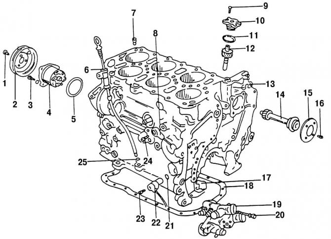
Fig. 69. Cylinder block with parts installed on it: 1 - bolt, 25 Nm; 2 - cooling pump pulley; 3 - bolt, 20 Nm; 4 - cooling system pump; 5 - O-ring, always replace with a new one; 6 - oil dipstick with guide tube; 7 - oil drain lock, 5 Nm; 8 - knock sensor #2 (to adjust the ignition timing); 9 - screw, 5 Nm; 10 - Oil pump drive cover; 11 - O-ring, always replace with a new one; 12 - oil pump drive; 13 - cylinder block; 14 - intermediate shaft; 15 - adjusting washer, the inscription on it should be facing up; 16 - bolt, 10 Nm; 17 - O-ring, always replace with a new one; 18 - oil pan gasket; 19 - thermostat housing; 20 - bolt, 10 Nm; 21 - O-ring, always replace with a new one; 22 - crankshaft speed sensor; 23 - bolt, 5 Nm; 24 - bolt, 20 Nm; 25 - O-ring seal
To remove the intermediate shaft, the engine must be removed from the vehicle. To remove the intermediate shaft, the drive 12 (Fig. 69) of the oil pump must be removed, since the pump is driven by the intermediate shaft.
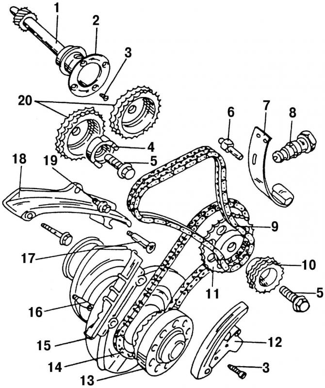
Fig. 91. Elements of the valve timing drive: 1 - intermediate shaft; 2 - leading ring; 3 - bolt, 10 Nm; 4 - sensor drive; 5 - bolt, 10 Nm; 6 - bolt, 25 Nm; 7 - elastic element of the tensioning device; 8 - double-row chain tensioner, 20 Nm; 9 - double row chain; 10 - double-row chain drive sprocket; 11 - single-row chain drive sprocket; 12 - chain tensioner with shoe; 13 - chain drive sprocket built into the crankshaft; 14 - single row chain; 15 - damper bar; 16 - special bolt, 25 Nm; 17 - pin with flange, 25 Nm; 18 - sedative; 19 - bolt, 20 Nm; 20 - crankshaft sprockets
After removing the timing drive parts (Fig. 91), the intermediate shaft becomes easily accessible, its mounting bolts can be unscrewed and the shaft removed.
The oil pump is installed in the reverse order of disassembly. It is necessary to ensure that there is an adjustment mark on the shaft guide ring. The ring should be screwed in such a way that the adjustment mark is at the top, otherwise it will not be possible to properly adjust the timing mechanism drive.
Visitor comments