



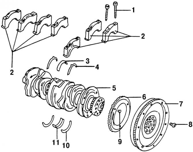
Fig. 82. Elements of the crankshaft and main bearings: 1 - bearing cap bolt; 2 - main bearing caps (main bearing No.1 - from the vibration damper side); 3 - main bearing shell; 4 - adjusting thrust half ring of bearing No.5; 5 - crankshaft; 6 - toothed rim of the speed sensor; 7 - flywheel; 8 - flywheel mounting bolt, always replaceable; 9 - toothed rim bolt; 10 - adjusting washer in the cylinder block for bearing No.5; 11 - cylinder block bearing insert. The toothed rim 6 of the speed sensor should always be replaced if it has been removed
- install the toothed rim 6 (Fig. 82) of the speed sensor with a new bolt 9 on the crankshaft;
- install the tubes into the oil channels of main bearings No.2 and 7 and fix them using a sharp punch;
- wipe the blind holes in the cylinder block seats and insert the bearing shells lubricated with engine oil (with lubrication grooves) so that the protrusions of the liners fit into the blind holes;
- insert thrust half rings into the middle main bearing seat (bearing no. 5);
Attention! The thrust half rings must be directed with their grooves towards the friction surface of the crankshaft.
- place the crankshaft in the bearing shells. If the connecting rods are in the cylinder block, install the connecting rod bearings on the crankshaft journals;
- insert the lower liners (without lubrication grooves) main bearings into the corresponding caps (protrusions into recesses) and generously lubricate their surfaces with motor oil;
- lubricate with engine oil and install, with the linings facing outwards, the other two thrust half rings on the bearing cover. The lubrication grooves should be located opposite the crankshaft;
- install the main bearing caps and tap them lightly with a rubber or plastic hammer;
- tighten the bearing cap bolts in several stages, starting with the middle one, to a tightening torque of 30 N·m. Then turn each bolt another half turn. After tightening the bearing caps, turn the crankshaft several times to make sure that it rotates easily, without jamming;
- check the axial free play of the crankshaft (see p. 2.6.1);
- install pistons and connecting rods (see p. 2.4.6);
- install the front and rear crankshaft oil seals (p. 2.6.4);
Caution! The front and rear crankshaft oil seals must be replaced after each removal of the crankshaft or oil seal flanges.
- lubricate the intermediate shaft bearing journal, install the shaft and tighten the mounting bolts to a tightening torque of 10 N·m;
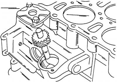
Fig. 79. Removing the oil pump drive shaft
- install the oil pump drive shaft with a new sealing ring (Fig. 79);
- install and adjust the timing drive, including the intermediate shaft chain (see p. 2.7.2);
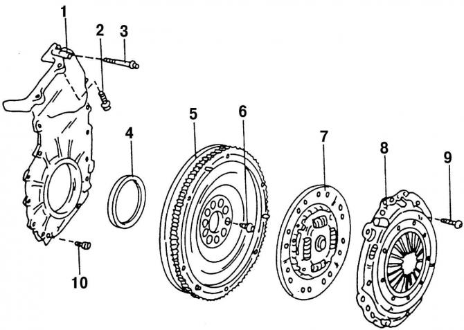
Fig. 85. Elements of the rear side of the engine: 1 - oil seal cover; 2 - bolt, 25 Nm; 3 - bolt, 10 Nm; 4 - oil seal; 5 - flywheel; 6 - flywheel mounting bolt; 7 - driven clutch disc; 8 - Clutch pressure plate; 9 - clutch basket mounting bolt, 20 Nm; 10 - bolt, 10 Nm
- lock the flywheel with a locking pin and install flywheel 5 (Fig. 85) on the crankshaft. Screw in new mounting bolts 6, tighten them to a torque of 70 N·m, then turn each bolt another quarter turn;
- install the clutch (see subsection 9.3) and tighten bolts 9 (Fig. 85) of the clutch pressure plate 8 to a torque of 20 N·m;
- install the oil pump (see p. 4.2.2);
- place a new gasket on the sealant and install the oil pan. Tighten the oil pan mounting bolts to 20 N·m.
Carry out all further work in the reverse order of disassembly.
Visitor comments