



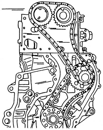
Fig. 16. VR6 engine camshaft drive
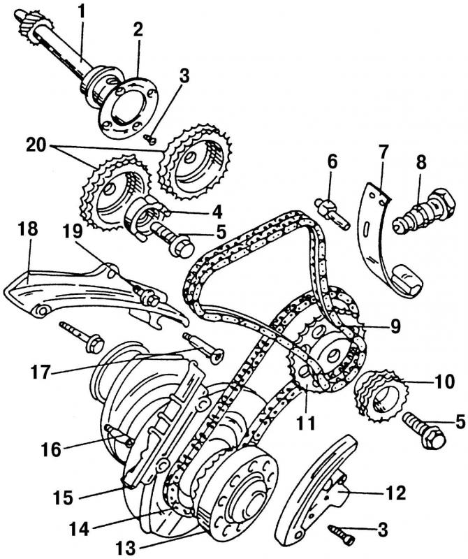
Fig. 91. Elements of the valve timing drive: 1 - intermediate shaft; 2 - leading ring; 3 - bolt, 10 Nm; 4 - sensor drive; 5 - bolt, 10 Nm; 6 - bolt, 25 Nm; 7 - elastic element of the tensioning device; 8 - double-row chain tensioner, 20 Nm; 9 - double row chain; 10 - double-row chain drive sprocket; 11 - single-row chain drive sprocket; 12 - chain tensioner with shoe; 13 - chain drive sprocket built into the crankshaft; 14 - single row chain; 15 - damper bar; 16 - special bolt, 25 Nm; 17 - pin with flange, 25 Nm; 18 - sedative; 19 - bolt, 20 Nm; 20 - crankshaft sprockets
Before dismantling the main parts of the timing drive (Fig. 91), it is necessary to remove all devices and units located on the front part of the engine so that only the elements of the timing drive remain unremoved (Fig. 16).
Before removing the timing drive components, set the piston of the first cylinder to the TDC position, and after removing the two timing drive chains, do not under any circumstances turn the crankshaft with the cylinder head removed, as this may cause the pistons to hit the valves.
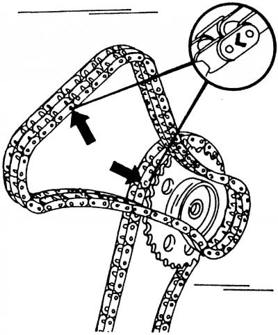
Fig. 92. Marking locations of camshaft drive chains (shown by arrows)
Before removing the chains, mark them with color in places (Fig. 92) in order to remember the direction of movement of the chains.
(The original material is available on the portal www.VWMANUAL.ru)
To reduce the tension of the double-row chain 9 (Fig. 91) of the gas distribution mechanism, loosen and remove the chain tensioner 8.
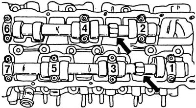
Fig. 93. Hexagons for fixing camshafts in a stationary position (shown by arrows)
To dismantle the double-row chain, first remove sprocket 20 (Fig. 91), located on one of the camshafts, or remove sprocket 10 from the intermediate shaft. In both cases, unscrew the sprocket mounting bolt 5. When unscrewing and tightening the mounting bolts of both sprockets, the camshafts must be fixed in a stationary position. To do this, hold the camshaft with a 24 mm open-end wrench placed on one of the hexagons (Fig. 93).
Loosen fastening bolt 5 (Fig. 91), remove sprocket 11 of the single-row chain together with the single-row timing chain. Remove all other timing drive parts (Fig. 91). When assembling, it is important to follow the recommended sequence of operations.
Visitor comments