
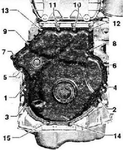
Timing chain covers
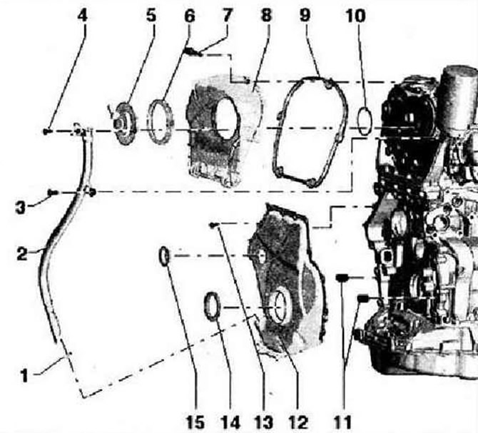
- 1 - O-ring, replace, lubricate before installation
- 2 - Oil dipstick guide tube
- 3 - Bolt, 9 Nm
- 4 - Bolt, 9 Nm
- 5 - Valve 1 for variable valve timing -N205-
- 6 - O-ring, lubricate before installation, replace if damaged
- 7 - Bolt
- 8 - Upper timing chain cover
- 9 - Gasket, replace if damaged
- 10 - O-ring, replace, lubricate before installation
- 11 - Center pins
- 12 - Lower timing chain cover
- 13 - Bolt, replace, follow tightening sequence
- 14 - Shaft seal for vibration damper, replace
- 15 - Plug, replace
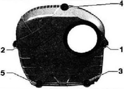
Upper timing chain cover - bolt tightening sequence
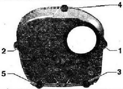
Tighten bolts -1...5- in 2 steps in the sequence shown.
- 1. Tighten the bolts first by hand.
- 2. Tighten the bolts to 9 Nm.
Lower timing chain cover - bolt tightening sequence
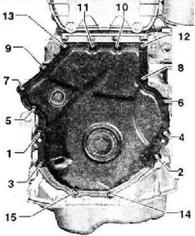
Tighten bolts -1... 15- in 2 stages in the sequence shown.
- 1. Tighten the screws to 8 Nm.
- 2. Tighten the screws by 45°.
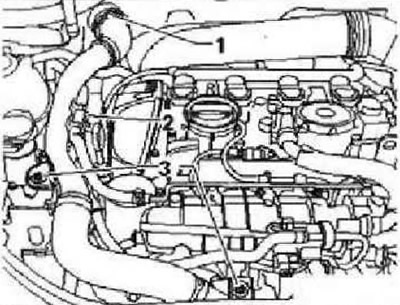
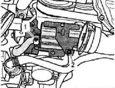
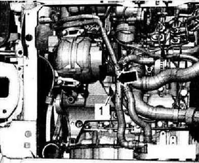
Removing and installing camshaft control valve 1 -N20S-
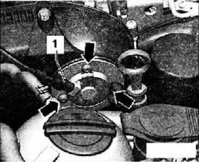
If equipped, remove the charge air duct to the resonator. Unplug connector for camshaft control valve 1 -N205- -1-. Remove screws -arrows- and remove camshaft control valve 1 -N205-.
Installation is carried out in the reverse order, while observing the following. Lubricate the O-ring and O-ring with engine oil.
Removal and installation of the upper protective cover of the drive chain
Vehicles with resonator only: Remove lock -1-, disconnect fuel lines -2- and unscrew bolt -3- for activated charcoal filter. Set aside the charge air pipe.
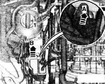
Cars with an absorber in the engine compartment
Remove air duct -1-, unlock absorber -A- and remove upwards -B-. Set aside the absorber.
All
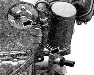
Push the coolant hoses aside and secure with binders. Unscrew screws -arrows- and remove dipstick guide tube from chain drive cover.
Remove camshaft control valve 1 -N205-. Release screws -1...5- and remove top cover for chain drive.
Installation
Lubricate the O-ring and O-ring with engine oil. Tighten the bolts in the sequence shown by hand. Tighten bolts to 9 Nm using torque wrench -VAG 1783- and 10 mm spanner -VAG 1783/1-. Further installation is carried out in the reverse order of removal.
Removal and installation of the lower protective cover of the drive target
Remove soundproofing. Remove the front right fender liner. Drain engine oil.
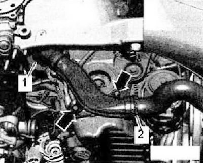
Vehicles with auxiliary heater
Detach clamp -1- and unscrew bolt -2-. Remove auxiliary heater muffler.
All
Remove screws -arrows-. Remove the air duct, to do this lift the clips -1 and 2-.
Caution: Risk of damage to a previously used V-ribbed belt if the belt is changed. For re-installation, before removing the V-ribbed belt, mark the direction of its running with chalk or a felt-tip pen.
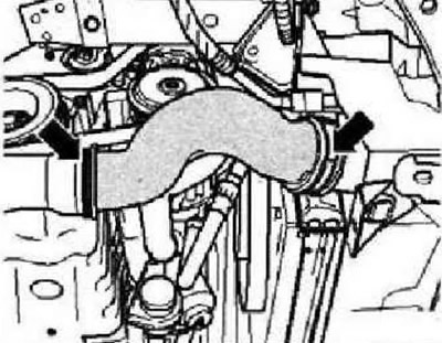
Remove right air hose -arrows-.
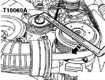
To loosen the V-ribbed belt, turn the tensioner from below in the direction of the - arrow. Secure belt tensioner with locking pin -T10060 A-. Remove poly V-belt from vibration damper pulley.
Turn vibration damper with stop -T10355- to position "TDC"-arrow-. The notch on the damper should be opposite the arrow mark on the bottom cover of the chain drives.
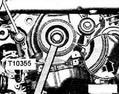
Caution: Risk of engine damage. In order not to adjust the valve timing, you can not turn the crankshaft with the bolt of the vibration damper removed from the TDC position.
Unscrew bolt for vibration damper, to do this use stop -T10355-. Remove vibration damper.
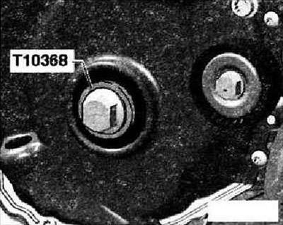
Caution: In order not to damage the toothing, only screw in the vibration damper bolt using bushing -T10368-.
Screw in vibration damper bolt and bushing -T10368- again. Remove engine cover. Remove air filter.
Caution: Risk of damage to electronic components when disconnecting the battery. Observe measures for disconnecting the battery.
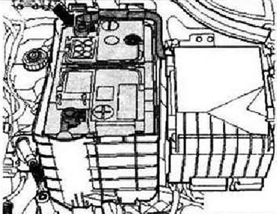
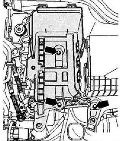
Disconnect earth wire -arrow- from battery with ignition switched off. Remove the battery. Remove battery holder -arrows-.
With automatic transmission
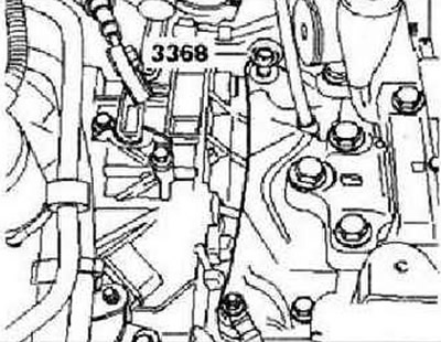
Screw eyebolt -3368- into gearbox as shown.
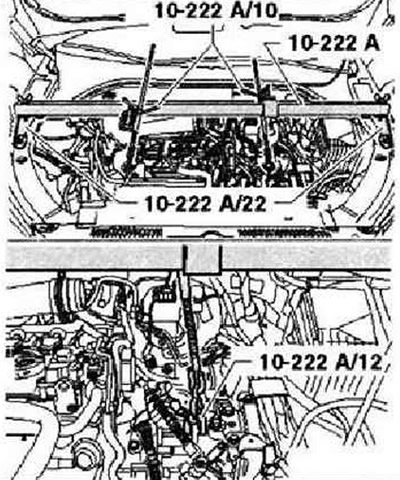
Install crosshead -10-222 A- with the following components: adapter -10-222 A /22- (2 pcs.), adapter -10-222 A /3- (2 pcs.), hook -10-222 A /10- (2 pcs.), earring -10-222 A /12-.
With manual transmission
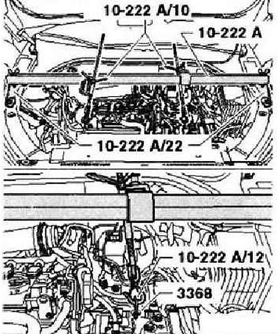
Remove the gearbox shift mechanism. Fit traverse -10 - 222 A- with the following components: adapter -10-222 A /22- (2 pcs.), adapter -10-222 A /3- (2 pcs.), hook -10-222 A /10- (2 pcs.), earring -10-222 A /12-.
All
Preload the motor with the spindle. Remove bolts -arrows- for power unit mounting on engine. Remove engine mount. Raise the engine about 50 mm and unscrew the upper engine mount bolt. Now lower the engine about 100 mm.
Release electrical wiring harness -arrow-. Remove bolt -1- and remove poly V-belt tensioner from accessory bracket. Unscrew lower engine mount bolts using chisel -T10099-. Remove the engine mount with bolts.
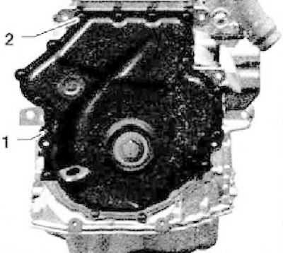
Unscrew screws -arrows- and remove dipstick guide tube from chain drive cover.
Unscrew charge pressure control solenoid valve -N75- from turbocharger -arrows-. Remove turbocharger union -1-.
Release screws -1...15-.
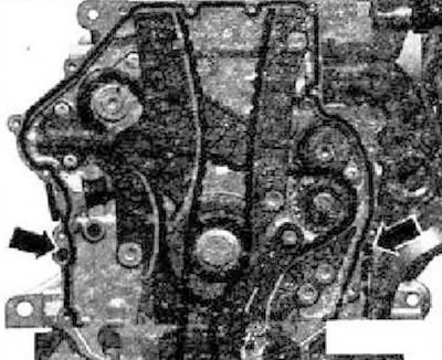
Caution: Risk of damage to the bottom cover of the belt drive. To avoid deformation, do not take it by the places between the points of the screw connections.
Press off lower cover for chain drive, starting at points -1 and 2-.
Installation
Sealant: silicone sealant -D 174 003 AE-.
Instructions: Pay attention to the expiration date of the silicone sealant. The cover must be installed within 5 minutes after applying the silicone sealant. Replace bolts that are tightened with an additional turn. Replace O-rings, gaskets and self-locking nuts.
Remove sealant residue on cylinder block with a flat scraper. Cover the shaft seal on both sides with adhesive tape to prevent dirt from getting into the shaft seal. Remove sealant residues from the cover using, for example, a hand-held electric drill with a rotating nozzle - a polymer brush. Clean the landing surfaces; they must be free of oil and grease. Fit cover with old bolts and tighten to 8 Nm. Use a feeler gauge to check the gap between the cover and the body, it should be no more than 0.2 mm.
Instruction: If this distance is more than 0.2mm, replace the cap. Do not measure the distance between the cover in the upper part of the oil pan, but make a visual inspection for evenness of the seating surface.
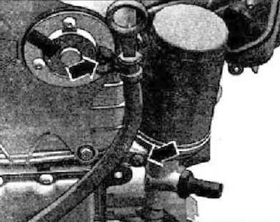
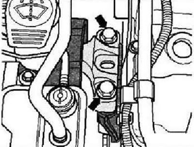
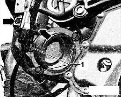
Check that both locating pins for centering the cover -arrows- are present.
Cut off the tip of the tube at the front mark (hole diameter about 3mm). Apply silicone sealant -D174 003 33- to the clean seating surface of the cover. Sealant bead thickness: 2...3 mm,
Instruction: The cover must be installed within 5 minutes after applying the silicone sealant. The sealant bead must not be thicker than the prescribed value, otherwise excess sealant may fall into the oil pan and clog the strainer in the oil pickup pipe.
Immediately install the cover and all bolts. Tighten bolts -1...15- in 2 stages in the sequence shown.
- 1. Tighten the screws to 8 Nm.
- 2. Tighten the screws by 45°.
Instructions: After mounting the cover, wait approximately 30 minutes for the sealant to dry. Only after that you can fill in engine oil.
Fill with engine oil. Check oil level. Further installation is carried out in the reverse order.
Visitor comments