



Caution: When performing installation work, especially in the engine compartment due to its dense layout, the following rules must be observed. Pipelines of all types (fuel, hydraulic, absorber, coolant, refrigerant, brake fluid, vacuum) and electrical wires must be routed as they were originally routed. To avoid damage to hoses, tubes or wires, ensure sufficient clearance when working with all moving or hot components. Insert new centering bushings into the cylinder block (for correct alignment of the engine and gearbox). Install the intermediate plate on the centering bushings of the "arrow" engine flange.
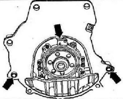
With manual transmission
Apply a thin layer of grease -G OO0100- to the splines of the input shaft.
With DSC
Replace the needle bearing in the crankshaft. Adjust the selector cable after installation.
All
When installing the power unit, make sure that it does not catch on the subframe or radiator. Electrical connection and wiring. Connect the tester -VAS 5051B-. Query the fault memory and delete all errors that may have occurred during the engine installation. Conduct a test drive. Then repeat the diagnostics of the vehicle systems and, if necessary, eliminate the errors that have arisen.
Instructions: After clearing the fault memory, a readiness code must be created.
Tightening torques
| M6 | 10 Nm |
| M7 | 15 Nm |
| M8 | 25 Nm |
| M10 | 40 Nm |
| M12 | 60 Nm |
Unit support
Instructions: The component support mounting bolts are flexible bolts and must be replaced.
Engine support
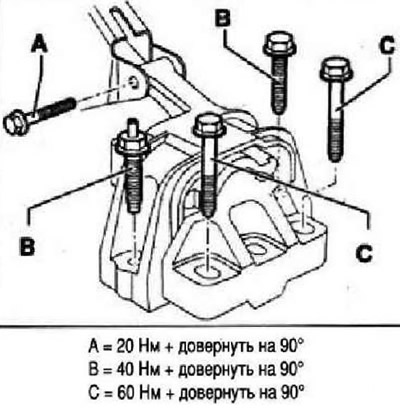
Transmission support
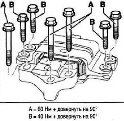
Swinging support
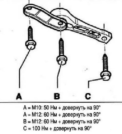
Checking the unit support adjustment
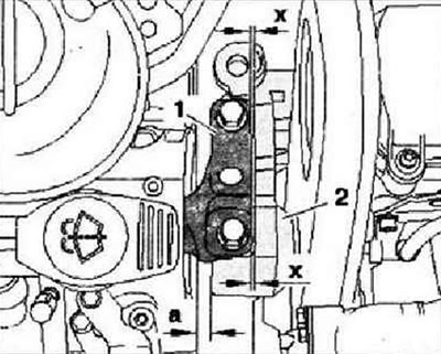
The distance "a" between the engine support and the right side member must be at least 10 mm. The cast edge in the engine support "2" must be parallel to the bracket "1". If these conditions are not met, the unit support must be adjusted.
Visitor comments