



Caution: When performing installation work, especially in the engine compartment due to its dense layout, the following rules must be observed. Pipelines of all types (fuel, hydraulic, absorber, coolant, refrigerant, brake fluid, vacuum) and electrical wires must be laid as they were originally laid. To avoid damage to hoses, tubes or wires, it is necessary to provide sufficient space when working with all moving or heated components.
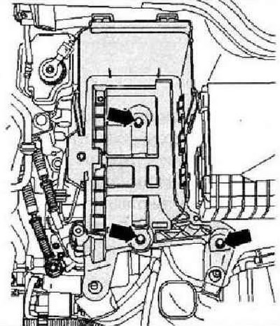
Before removal, interrogate the fault memory of all control units. Disconnect the ground wire from the battery with the ignition off. Remove the engine casing.
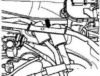
Remove the air filter. Remove the battery and battery holder frame. Remove the windshield wiper arms. Remove the water drain box trim. Remove the left engine wiring harness connector from the engine control unit. Unlock the engine wiring harness entry "arrow" and remove upwards.
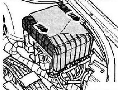
Remove the cover of the switching unit in the engine compartment by moving both fasteners in the direction of the arrow.
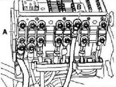
Disconnect the cable from the generator "A" and the cable from the battery "B" on the fuse bracket.
Unscrew the ground cable from the side member "arrow".
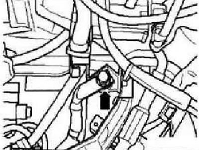
Open the cable duct clamps on the "arrow" side member.
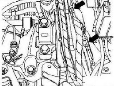
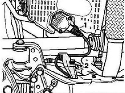
Release and disconnect electrical connector "1". Open the wiring holder "2" located underneath. Remove the wiring harness to the engine control unit from the wiring holder and place it on the engine.
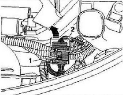
Remove the gearshift mechanism. Clamp the hose to the clutch master cylinder using clamp "3094".
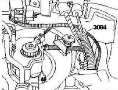
Pull out the pipeline "arrow" bracket until it stops.
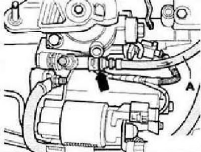
Remove the pipe from the fan/slave cylinder and plug it.
Caution: Do not press the clutch pedal again.
With automatic transmission
Remove the selector cable from the gearbox. Disconnect the lines to the gearbox oil cooler from the gearbox.
With DSG
Remove the selector cable from the gearbox.
All
Disconnect electrical connector "2".
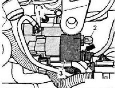
Unscrew the upper mounting bolts of the "arrow" air intake.
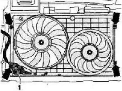
Disconnect the hose clamp "2". Unscrew the bolt "4". Disconnect the electrical connector "arrow" and release the electrical wire.
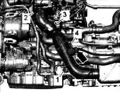
CAUTION: Risk of scalding from hot steam and heated coolant.
Open the coolant expansion tank cap. Remove the noise insulation screen. Remove the front part of the mudguards or the front mudguards. Remove the boost air hoses "arrows".
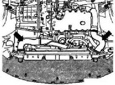
Unscrew bolt "1" and remove the air duct downwards. Disconnect connector "1" and unscrew the lower fastening bolts "arrows" of the air intake. Remove the air intake in the downward direction. Disconnect electrical connector "2" of the coolant temperature sensor at the radiator outlet "G83".
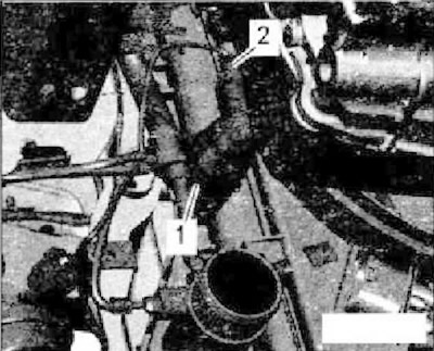
Place the -VAS 6208- oil pan under the engine. Drain the coolant.
Remove coolant hoses -1 and 2-.
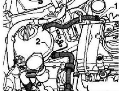
CAUTION: The fuel pressure line is under pressure!
Disconnect the lines at the fuel transfer points.
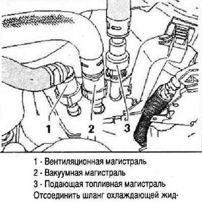
Disconnect the coolant hose from the radiator on the right and the coolant hose from the radiator on the left. Remove the coolant hoses to the heater heat exchanger "arrows", to do this, slightly loosen the locking bracket.
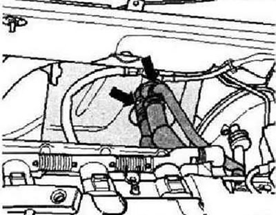
Unscrew the accessible nuts "arrows" from above connecting the exhaust inlet pipe to the turbocharger.
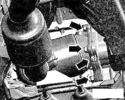
Remove the vacuum hoses "arrows".
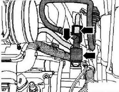
Front wheel drive cars
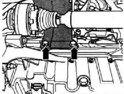
Unscrew the heat shield of the right drive shaft "arrow".
All
Remove the drive shafts. Remove the exhaust manifold inlet pipe with the catalytic converter.
Caution. Risk of damage to previously used poly V-belt when changing its running direction. To reinstall the poly V-belt, mark its running direction with chalk or felt-tip pen before removing it.
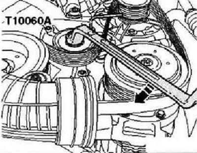
To loosen the poly V-belt, turn the tensioner from below in the -direction of the arrow-. Secure the belt tensioner with the locking pin -T10060 A-. Remove the poly V-belt.
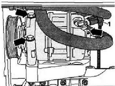
Disconnect electrical connector "1" of the air conditioning compressor regulating valve "N₂80".
CAUTION: Risk of injury from coolant. Do not allow the air conditioning system refrigerant circuit to become depressurized.
Unscrew the air conditioning compressor "arrow" bolts "1".
Caution: Risk of damage to refrigerant lines and hoses. Do not twist, break or bend refrigerant lines and hoses.
Tie the air conditioning compressor with the hoses connected to the side member from above.
All
Unscrew bolt "2" on the coolant recovery pump bracket "V51".
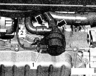
Instructions: The coolant recovery pump "V51" remains in the installation position.
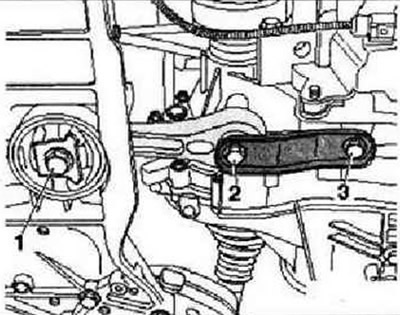
Unscrew bolts -1...3- and remove the pendulum support.
[View the original on the website: vwmanual]
If present, disconnect electrical connector "1" of oil temperature and level sensor "G266" and remove holder "2" from subframe. Disconnect all other wires that need to be disconnected from engine and gearbox and set them aside. Disconnect all connecting, vacuum, inlet hoses, coolant supply and outlet hoses from engine.
Screw the engine bracket "T10359" with bolt "1" to the cylinder block with a torque of 20 Nm.
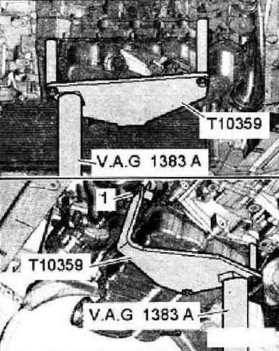
Instructions: Threaded hole for bolt "1" is intended for screwing on the coolant run-out pump "V51".
Place the tilting device -VAG 1383 A- under the engine bracket "T10359". Raise the engine with the gearbox a little.
Instructions: To unscrew the powertrain suspension bolts, use the VAS 5035 stepladder,
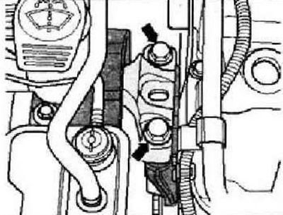
Unscrew the "arrow" bolts of the power unit suspension on the engine,
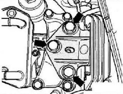
Unscrew the "arrow" bolts of the power unit suspension on the gearbox.
Instructions: Check that all hoses and wires between the engine, body and gearbox are disconnected. To avoid damage, lower the engine with the gearbox carefully.
Dual Clutch Transmission
Pay attention to the automatic transmission selector cable.
All
Pull the power unit forward as far as possible and slowly lower it down. For installation work, the engine must be secured to the tilting device -VAS6095-.
Visitor comments