
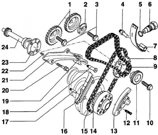
- 1 - camshaft sprocket;
- 2 - pulse rotor for the Hall sensor;
- 3 - camshaft sprocket bolt, 100 Nm. Before screwing in the bolt, lubricate the underside of the bolt head with a thin layer of engine oil. When tightening the bolt, keep the camshaft from turning with a SW 24 wrench;
- 4 - pivot pin, 18 Nm;
- 5 - sealing ring. If damaged, use a new O-ring;
- 6 - chain tensioner, 40 Nm;
- 7 - strap tensioner;
- 8 - drive chain sprocket;
- 9 - two-row bush-roller chain. Before removing the chain, note the direction of rotation of the chain;
- 10 - bolt, 100 Nm;
- 11 - drive chain sprocket;
- 12 - bolt, 10 Nm;
- 13 - chain tensioner with strap. Before removing the chain tensioner, use a screwdriver to release the locking gear and separate the chain guide from the tensioner. The engine may only be cranked with the chain tensioner installed;
- 14 - chain drive sprocket. At TDC on cylinder 1, the sheared tooth should be in line with the #1 main bearing cap connector;
- 15 - single-row roller chain. Before removing the chain, note the direction of rotation of the chain;
- 16 - damper bar;
- 17 - pin for damper bar, 10 Nm;
- 18 - guide pin with shoulder, 10 Nm;
- 19 - bolt, 20 Nm. The bolt is installed using a special tool VW-D6;
- 20 - bolt, 20 Nm;
- 21 - damper bar;
- 22 - bolt, 20 Nm. The bolt is installed using a special tool VW-D6;
- 23 - adjusting washer;
- 24 - intermediate shaft
The location of the elements of the gas distribution mechanism when the piston of the first cylinder is installed at top dead center in the compression stroke
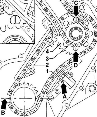
- 1 - chain;
- 2 - chain guide;
- 3 - front sprocket of the intermediate shaft;
- 4 - rear sprocket of the intermediate shaft;
- And - a clamp of the mechanism of a tension of a chain;
- B - the adjusting tooth on the crankshaft sprocket must be in line with the No. 1 main bearing cap connector;
- C - alignment mark on the intermediate shaft sprocket;
- D - alignment mark on the intermediate shaft sprocket
Marking locations before removing timing chains
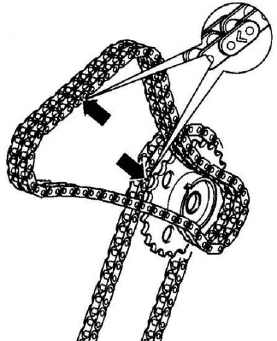
Before removing the timing chains, use paint to mark the chains at the locations shown in the figure.
The camshafts are driven from the crankshaft, not directly, but through an intermediate sprocket. An asterisk of smaller diameter is fixed on one shaft with an intermediate sprocket, through which the second chain is also actuated by the gas distribution mechanism. The upper camshaft timing chain is tensioned by a plate tensioner, which is held in position by an external adjusting bolt. The lower timing chain has a hydraulic tensioner that does not require adjustment.
Removing
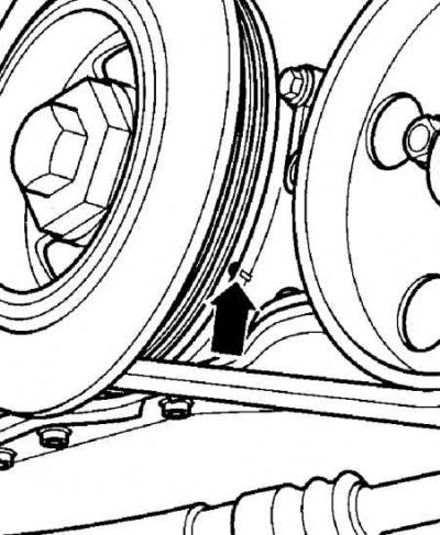
1. Turn the crankshaft of the engine to such a position that the piston of the first cylinder is at top dead center. In this case, the installation mark (arrow) on the crankshaft pulley/damper should align with the pointer on the chain case.
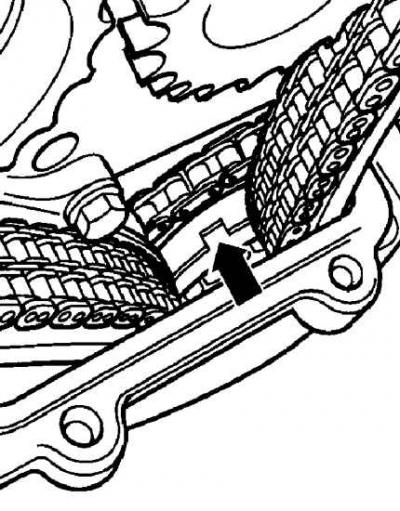
2. When installing the piston of the first cylinder at TDC, a groove should be visible on the sprockets of the intermediate shaft (indicated by an arrow). If the slot on the intermediate shaft sprocket is not visible, turn the engine crankshaft one full revolution and re-align the alignment marks with the pointers.
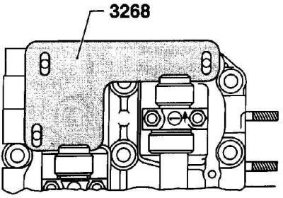
3. Fix the camshafts by inserting the special tool VW-3268 into the grooves of the camshafts.
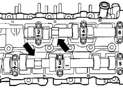
4. When unscrewing the camshaft sprocket bolt, using a wrench, by the flats (indicated by arrows) keep the camshaft from turning.
Visitor comments