
If only checking/adjusting the start of the fuel supply is to be carried out, then all work steps must be carried out, except for the removal of the toothed belt.
Visual inspection of the toothed belt
Remove the toothed belt cover and inspect the belt. The belt must be free of the following damage:
- base cracks (cracks, frame failures, cross-sectional failures);
- bundle (cover layer, tourniquet);
- local tear at the base;
- fringing tourniquet;
- lateral wear (wear, fringing, hardening of the side surfaces - vitreous sidewalls, surface cracks);
- traces of oil and grease.
Removing
Remove upper toothed belt cover.
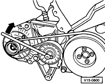
Use chalk to mark the direction of movement of the toothed belt with an arrow so that this direction is maintained during the subsequent installation of the belt. On a supercharged diesel engine, use a screwdriver to press off the tensioner pulley cover and, turning the socket wrench SW13 in the direction of the arrow, loosen the pulley tension. For other engines, release and remove the V-belt.
Remove the V-belt pulley and lower toothed belt guard.
Set the crankshaft to the TDC position for cylinder 1. To do this, shift the gearbox to neutral and, using a wrench with a replaceable socket head, turn the crankshaft by the central bolt of the belt pulley until it reaches the TDC position for cylinder 1 (arrow).
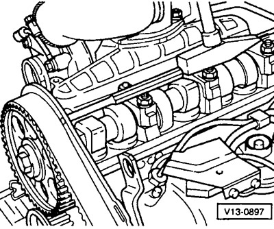
The crankshaft is in the TDC position for cylinder 1 when both lobes of the camshaft for that cylinder are pointing up.
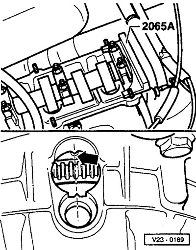
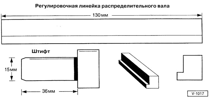
Lock the camshaft in this position using the 2065A adjusting bar. If this special tool is not available, fabricate it according to drawing V-1017.
Insert the adjusting ruler into the groove of the camshaft. Adjusting ruler (VW 2065A) has a protrusion that fits into the groove and prevents the camshaft from turning.
Align the adjusting bar parallel to the cylinder head. To do this, turn the locked camshaft so that one end of the adjusting bar rests on the cylinder head. From the other end of the ruler, measure the resulting gap with the help of probes. Insert a feeler gauge half the measured gap between the adjusting bar and the cylinder head. After that, turn the camshaft so that the adjusting ruler rests on the inserted probe. Insert a second feeler gauge of the same thickness between the adjusting ruler and the cylinder head from the other end of the ruler.
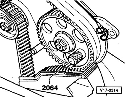
Now you need to insert the locking pin 2064 into the holes of the gear wheel of the injection pump and the bracket of the injection pump. The pin fixes the position of the gear wheel of the injection pump. You can make the pin yourself in accordance with Figure V-1017.
Attention: For 75 hp engine. since 10/94 (AAZ) locking pin 3359 required.
If the pin does not fit into the hole in the injection pump bracket, the valve timing must be adjusted again.
75 hp engine since 10/94 (AAZ): Loosen the 3 bolts securing the injection pump sprocket.
Loosen the tension roller nut and loosen the toothed belt tension.
Supercharged diesel engine: Remove tensioner pulley.
Attention: The tensioner pulley must be replaced every time the toothed belt is replaced.
Supercharged diesel engine: Fit new eccentric tensioner pulley and screw firmly by hand. In this case, the tension roller must be in the released state.
With semi-automatic tensioner pulley: remove guide pulley -9-, see drawing no. 130028 on previous page.
Use chalk to mark the direction of movement of the toothed belt with an arrow so that the next time the belt is installed (if the same belt is installed) keep this direction. Remove toothed belt.
Note: When the camshaft is turned with the toothed belt removed, neither piston should be at TDC. Otherwise serious damage to the pistons or valves may occur. If the camshaft needs to be rotated, then all the pistons must first be retracted approximately the same distance from the TDC position. To do this, make a chalk mark on the top of the crankshaft pulley (the crankshaft must be in the position where the piston of cylinder 1 is at TDC). Then turn the crankshaft pulley 1/4 turn (90°) right or left. The marking on the belt pulley must then point to the right or left respectively.
Installation
Through the hole in the gearbox, check whether the TDC mark on the flywheel matches the alignment mark.
Loosen the camshaft sprocket bolt about 1/2 turn. Drive the camshaft sprocket off the camshaft cone by hammering with a rod through the 6mm hole in the rear toothed belt guard.
Fit toothed camshaft drive belt. If a used toothed belt is refitted, the previously marked arrow must point in the same direction.
Engines up to 9/93 (without semi-automatic tensioner) tension toothed belt, see above.
With a semi-automatic tensioning roller: install the guide roller, tighten it to a torque of 25 Nm.
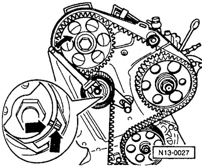
Engines from 10/93 with semi-automatic tensioner: turn the tensioner with a suitable wrench (e.g. Matra V159) to the right until the spline and lug are opposite each other (arrow). Now the tension of the toothed belt is maintained constant by the tension roller.
Tighten the tensioning roller nut to 20 Nm.
Check the mark on the flywheel that the crankshaft is at TDC for cylinder 1, then tighten the camshaft gear bolt to 45 Nm.
75 hp engine since 10/94 (AAZ): Tighten the 3 bolts for the gear wheel of the injection pump to 25 Nm.
Remove the camshaft shim and the injection pump sprocket lock pin.
Engines up to 9/93: check toothed belt tension again to ensure correct tension, tighten belt if necessary.
75 hp engine since 10/94 (AAZ): Turn crankshaft 2 turns in direction of rotation and set cylinder 1 to TDC again. Secure injection pump sprocket with locking pin. If this is not possible, then loosen the fastening bolts and turn the hub of the gear wheel of the injection pump to a position in which the pin can fix it. In this position, tighten the injection pump sprocket bolts to 25 Nm.
Install lower toothed belt guard and V-belt pulley. Attach V-belt and tighten. Replace seal on cylinder head cover, screw on cylinder head cover 1. Tighten bolts to 10 Nm. Install the upper toothed belt cover.
Engines other than 75 hp engine since 10/94 (AAZ): check the start of injection pump supply, see below.
Visitor comments