



Engine management system «Digifant» Volkswagen Passat B4

Integrated engine management system «DIGIFANT»
Cars with engines "RV" and "2E" are equipped with the integrated engine management system (ECMS) "Digifant" by Volkswagen. ECMS is designed to control fuel injection and ignition...
Cars with engines "RV" and "2E" are equipped with the integrated engine management system (ECMS) "Digifant" by Volkswagen. ECMS is designed to control fuel injection and ignition...

Fuel injection control subsystem
The fuel injection control subsystem KSUD "Digifant" is developed on the basis of the distributed control system (multipoint) electronically controlled injection "LE-Jetronic" by...
The fuel injection control subsystem KSUD "Digifant" is developed on the basis of the distributed control system (multipoint) electronically controlled injection "LE-Jetronic" by...

Checking and adjusting engine idle speed
Before adjusting and checking the engine idle speed, the following must be done: warm up the engine (oil temperature not less than 80°C); turn off electrical consumers, including...
Before adjusting and checking the engine idle speed, the following must be done: warm up the engine (oil temperature not less than 80°C); turn off electrical consumers, including...

Checking the Idle Speed Control Solenoid Valve
The operability of the electromagnetic idle stabilization valve is checked on a warmed-up engine (oil temperature no higher than 80°C), with the engine idle speed correctly...
The operability of the electromagnetic idle stabilization valve is checked on a warmed-up engine (oil temperature no higher than 80°C), with the engine idle speed correctly...

Checking the supply voltage of the idle and full load switches on vehicles with a «PB» engine
Disconnect the switch connector (fig. 2-105). connect the voltmeter to terminals "1" and "2" of the plug part 2 of the connector. Turn on the ignition and check the supply voltage...
Disconnect the switch connector (fig. 2-105). connect the voltmeter to terminals "1" and "2" of the plug part 2 of the connector. Turn on the ignition and check the supply voltage...

Checking and adjusting the idle switch on the RV engine
Disconnect the idle and full load switches. Connect an ohmmeter to terminals "1" and "2" (fig. 2-106) switch pads. Resistance on the ohmmeter should be 0 Ohm (the switch contacts...
Disconnect the idle and full load switches. Connect an ohmmeter to terminals "1" and "2" (fig. 2-106) switch pads. Resistance on the ohmmeter should be 0 Ohm (the switch contacts...

Checking and adjusting the full load switch on the RV engine
Disconnect the idle and full load switches. Connect an ohmmeter to terminals "2" and "3" of the switch block. Fasten to the throttle shaft 1 (fig. 2-107) goniometer with arrow...
Disconnect the idle and full load switches. Connect an ohmmeter to terminals "2" and "3" of the switch block. Fasten to the throttle shaft 1 (fig. 2-107) goniometer with arrow...

Checking the forced-run and mixture enrichment system with the throttle valve fully open on the RV engine
Warm up the engine (oil temperature not less than 80°C) and let it idle. Manually close the contact of the full load switch of the throttle valve. Using a screwdriver, move the...
Warm up the engine (oil temperature not less than 80°C) and let it idle. Manually close the contact of the full load switch of the throttle valve. Using a screwdriver, move the...

Checking the fuel pressure regulator and residual fuel pressure
On vehicles with an RV engine, cover the plug at the end of the fuel line with a rag to avoid injury from a jet of pressurized fuel. Place a container under the fuel line to...
On vehicles with an RV engine, cover the plug at the end of the fuel line with a rag to avoid injury from a jet of pressurized fuel. Place a container under the fuel line to...

Fuel pump
Note: Removal, installation and performance testing of the fuel pump is carried out in the same way as described in the system "Mono-Jetronic". The pump capacity should be, cm³/30...
Note: Removal, installation and performance testing of the fuel pump is carried out in the same way as described in the system "Mono-Jetronic". The pump capacity should be, cm³/30...

Checking the air flow meter
Disconnect air duct 1 from the air flow meter and disconnect the meter connector (fig. 2-113). Connect the ohmmeter to terminals "3" and "4" of the meter block and check the...
Disconnect air duct 1 from the air flow meter and disconnect the meter connector (fig. 2-113). Connect the ohmmeter to terminals "3" and "4" of the meter block and check the...

Checking the coolant temperature sensor
Disconnect the blue connector from the coolant temperature sensor (fig. 2-114) fuel injection control subsystem. Relieve residual pressure in the engine cooling system. Remove the...
Disconnect the blue connector from the coolant temperature sensor (fig. 2-114) fuel injection control subsystem. Relieve residual pressure in the engine cooling system. Remove the...

Checking the incoming air temperature sensor
Disconnect the air flow meter connector (fig. 2-113), connect an ohmmeter to terminals "1" and "4" and check that the ohmmeter readings correspond to the values indicated on the...
Disconnect the air flow meter connector (fig. 2-113), connect an ohmmeter to terminals "1" and "4" and check that the ohmmeter readings correspond to the values indicated on the...

Checking the injectors
Check the supply voltage of the injectors. To do this: disconnect the fuel line connector: connect the LED tester to the terminals of the line connector: turn on the starter. The...
Check the supply voltage of the injectors. To do this: disconnect the fuel line connector: connect the LED tester to the terminals of the line connector: turn on the starter. The...

Checking the starting injector on the «2E» engine
Check the supply voltage of the starting injector. To do this: turn on the ignition; disconnect the fuel line and starting injector connectors, connect the LED tester to the...
Check the supply voltage of the starting injector. To do this: turn on the ignition; disconnect the fuel line and starting injector connectors, connect the LED tester to the...
Checking the intake manifold heater
Disconnect the vacuum hose of the pneumatic drive from the thermostat. Disconnect the lower and upper parts of the air filter housing and remove the filter element. Check the...
Disconnect the vacuum hose of the pneumatic drive from the thermostat. Disconnect the lower and upper parts of the air filter housing and remove the filter element. Check the...

Checking the oxygen sensor in the exhaust gases
Warm up the engine to a temperature of at least 80°C, check that the idle speed corresponds to the required value, ensure that the exhaust system is tight, ensure that the coolant...
Warm up the engine to a temperature of at least 80°C, check that the idle speed corresponds to the required value, ensure that the exhaust system is tight, ensure that the coolant...
Checking the electrical circuits of the KSUD «DIGIFANT»
Warning: Do not connect the measuring instrument probes (ohmmeter or voltmeter) to the connector terminals. It is recommended to connect the device to the supply wires from the...
Warning: Do not connect the measuring instrument probes (ohmmeter or voltmeter) to the connector terminals. It is recommended to connect the device to the supply wires from the...
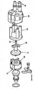
Ignition Timing Control Subsystem
The ignition advance angle control subsystem is controlled by the KSUD controller. This achieves high accuracy of ignition timing control, improves engine operation at idle and...
The ignition advance angle control subsystem is controlled by the KSUD controller. This achieves high accuracy of ignition timing control, improves engine operation at idle and...

Adjustment of the fuel injection control subsystem of the Passat GT 1.8 G60 Syncro vehicles
Fig. 1. Placement of elements of the fuel injection control subsystem KSUD "Digifant G60" in the engine compartment: 1 — Evaporative canister shut-off valve: 2 — Fuel pressure...
Fig. 1. Placement of elements of the fuel injection control subsystem KSUD "Digifant G60" in the engine compartment: 1 — Evaporative canister shut-off valve: 2 — Fuel pressure...

Spiral supercharger «G60» of cars «Passat GT 1.8 G60 Syncro»
Fig. 15. Supercharger "G60": 1, 2 - halves of the supercharger body with spiral channels; 3 - movable displacer; 4 - eccentric drive shaft; 5 — eccentric shaft of plane-parallel...
Fig. 15. Supercharger "G60": 1, 2 - halves of the supercharger body with spiral channels; 3 - movable displacer; 4 - eccentric drive shaft; 5 — eccentric shaft of plane-parallel...
This section is available on russian, bulgarian, belarusian, ukrainian, serbian, croatian, romanian, polish, slovak, hungarian
Passat B6
Passat B5
Passat B4
Passat B3
Passat B2
- General information
- User manual
- Maintenance
- Petrol engine 1.6L
- Engine repair
- Cooling and lubrication system
- Fuel injection system
- Petrol engine 2.0L
- Engine repair
- Lubrication system
- Cooling system
- Fuel and exhaust systems
- Diesel engine 2.0L
- Engine repair
- Cooling and lubrication system
- Fuel and exhaust systems
- Transmission
- Clutch
- Mechanical gearbox
- Automatic gearbox
- Drive shafts
- Chassis
- Wheels and tires
- Car suspension
- Steering
- Brake system
- Body
- Exterior (external elements)
- Electrical equipment
- Power devices
- Lighting and appliances
- Electrical circuits
- General information
- User manual
- Weekly checks
- Maintenance
- Power unit
- Engine repair
- Cooling system
- Fuel system (petrol)
- Fuel system (diesel)
- Engine management
- Exhaust system
- Transmission
- Clutch
- Car gearbox
- Drive shafts
- Chassis
- Car suspension
- Wheels and tires
- Steering
- Brake system
- Body
- Exterior (external elements)
- Interior (internal elements)
- Doors and covers
- Ventilation and heating
- Electrical equipment
- Power devices
- Lighting and appliances
- Electrical circuits
- General information
- User manual
- Maintenance
- Technical data
- 8-valve engine
- Engine repair
- Cooling and lubrication system
- Supply system
- Ignition system
- Fuel injection «Mono-Jetronic»
- Control system «Mono-Motronic»
- Control system «Digifant»
- Control system «Simos»
- 16-valve engine
- Engine repair
- Cooling and lubrication system
- Fuel injection «K-Jetronic»
- Control system «KE-Motronic»
- Control system «Digifant»
- Diesel engine
- Engine repair
- Cooling and lubrication system
- Power and control system
- Turbocharging system
- Digital control system
- Transmission
- Clutch
- Manual gearbox
- Hydromechanical gearbox
- Front wheel drive
- Chassis
- Car suspension
- Steering
- Brake system
- Body
- Body elements
- Electrical equipment
- Power devices
- Lighting and appliances
- Electrical circuits
- General information
- User manual
- Driving Tips
- Maintenance instructions
- Technical data
- Power unit
- Engine repair
- Ignition system
- Lubrication system
- Cooling system
- Supply system
- Petrol injection system
- Diesel engine
- Exhaust system
- Transmission
- Clutch
- Car gearbox
- Chassis
- Suspension
- Steering
- Brake system
- Wheels and tires
- Body
- Exterior
- Interior
- Heating system
- Electrical equipment
- Power devices
- Lighting system
- Equipment and devices
- Wiper system
- Electrical circuits
- General information
- Introduction to instructions
- User manual
- Power unit
- Engines 4-cylinder FZ
- Engines 4-cylinder
- Engines 5-cylinder
- Transmission
- Clutch
- Four-speed gearbox
- Five-speed gearbox
- Hydromechanical gearbox
- Front wheel drive
- Chassis
- Front suspension
- Rear suspension
- Steering
- Brake system
- Body
- Body elements
- Electrical equipment
- Equipment and devices
- Electrical circuits