
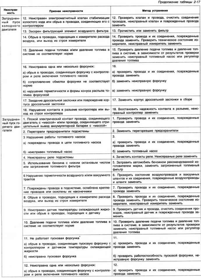
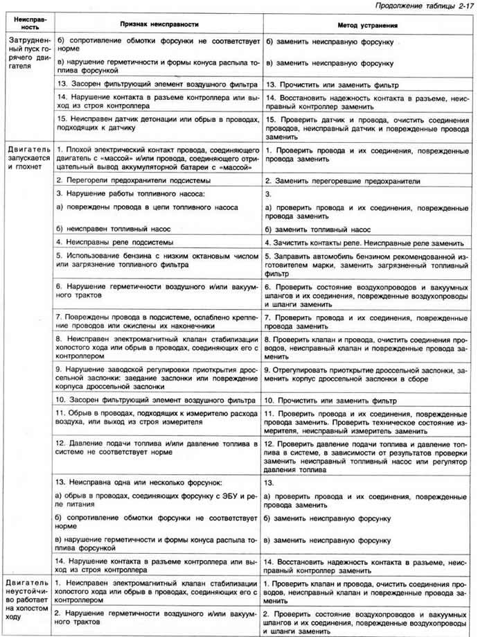
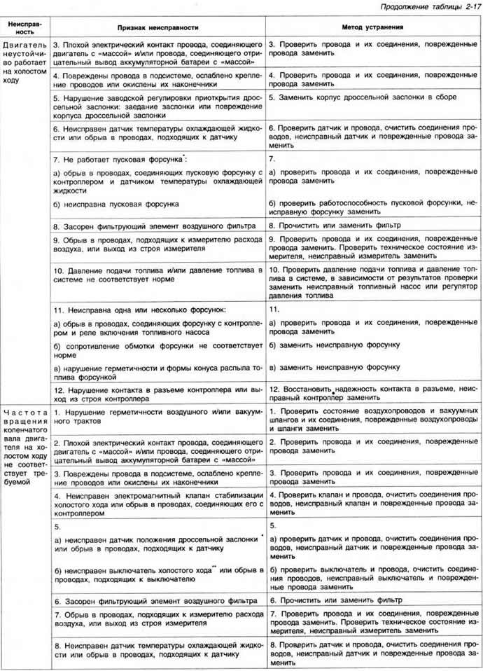
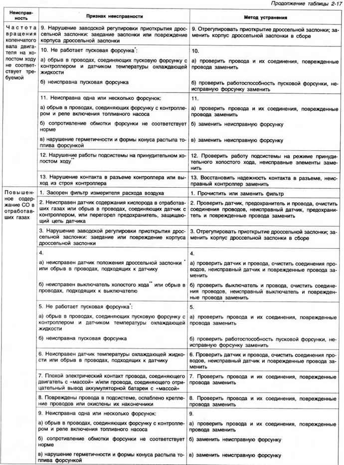
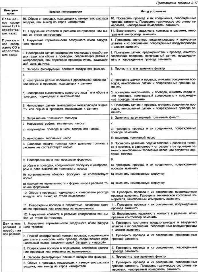
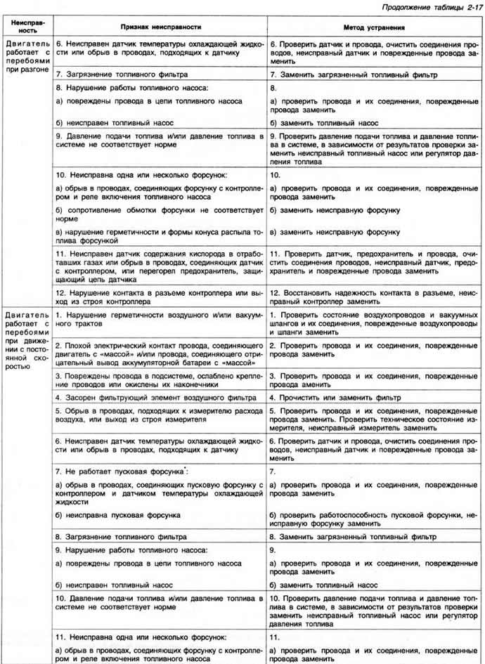
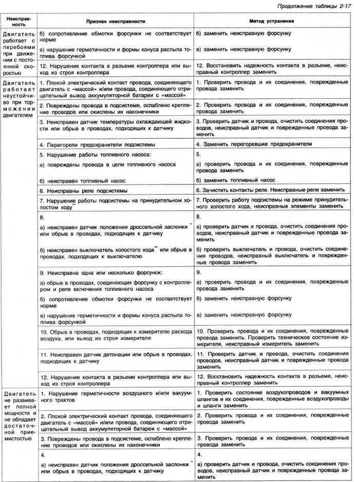
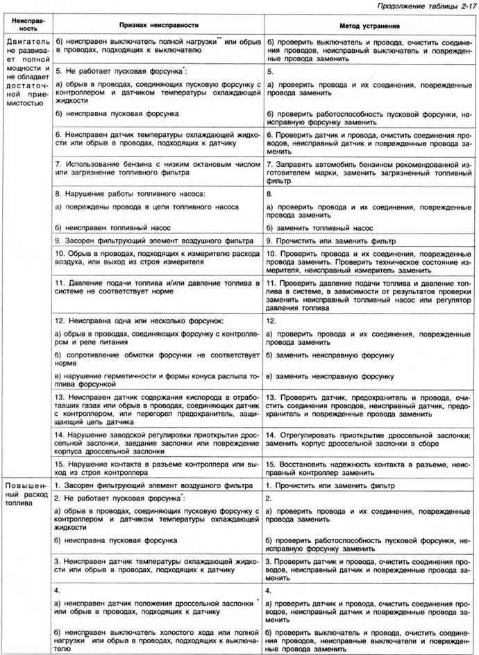
Design features and principle of operation
The ignition timing control subsystem includes an ignition distributor with a Hall sensor (pic. 2-118), switch, high energy ignition coil, spark plugs and knock sensor.
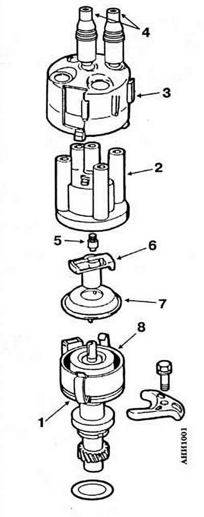
Pic. 2-118. Engine Ignition Distributor Parts «RV» and «2E»:
1 - body;
2 - cover;
3 - noise suppression screen;
4 - interference suppression tips of wires;
5 - coal;
6 - distributor rotor;
7 - protective screen;
8 - toothed anchor.
The Hall sensor provides the controller with an engine speed signal.
The air flow meter provides the controller with information about the instantaneous engine load.
The controller processes information about the crankshaft speed and engine load in accordance with the programmed ignition timing control characteristic and issues appropriate control signals to the ignition switch.
When the engine is idling, the controller receives a throttle position signal from the throttle sensor or sensors. If the throttle valve is closed, the ignition timing is determined depending on the speed of the crankshaft and the characteristics of the engine with the least load. If the throttle valve is open, the ignition timing is developed depending on the engine speed in accordance with the engine load. The knock sensor sends signals to the controller when detonation occurs in the engine cylinders. In this case, the controller reduces the ignition timing in the corresponding cylinder by 4°. If the detonation in this cylinder does not stop, the ignition timing decreases in all cylinders. After knocking stops, the controller gradually increases the ignition timing again until knocking occurs, and the control cycle is repeated.
Warning. To prevent failure of the ignition devices and in particular the controller, observe the following safety rules:
- it is forbidden to disconnect and connect the wires of the ignition system and the fuel injection system with the ignition on:
- when checking the compression pressure in the engine cylinders, disconnect the high-voltage wire of the ignition coil and connect it to «weight»;
- when starting the engine using an accelerated battery charger, connect the device for no more than 1 minute, and the voltage of the device should not exceed 16.5 V;
- when performing electric welding on the engine, disconnect both wires from the battery;
- when towing a car, disconnect the connector of the ignition switch;
- use only 1 kΩ resistance spark plug wires and 5 kΩ spark plug tips;
- it is forbidden to wash the car and the engine with the ignition on.
Removal and installation of the distributor of ignition
Removal and installation of the distributor of ignition is made, as it is specified above in subsection «Engine ignition system «EZ» and «RP».
Checking and setting the initial ignition timing
Start and warm up the engine (oil temperature not less than 80°С) and stop the engine.
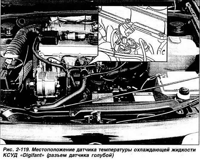
Connect a stroboscope to the ignition distributor in accordance with the operating instructions and a control tachometer. Start the engine at idle Disconnect the blue connector of the coolant temperature sensor located on the cylinder head (pic. 2-119).
Check the ignition timing at an idle speed of 2000-2500 rpm by directing the strobe light beam to the ignition timing marks.
By turning the distributor housing, achieve alignment of marks on the flywheel and cylinder block within the limits specified in subsection «Design and specifications».
Connect the coolant temperature sensor connector.
Press the accelerator pedal sharply several times. then check the ignition timing again and, if necessary, repeat the adjustment.
Checking ignition timing and knock sensor
The engine oil temperature must be at least 80°C, the coolant temperature sensor must be in good condition.
Connect a stroboscope to the ignition distributor in accordance with the operating instructions and a control tachometer. Start the engine at idle. Disconnect the coolant temperature sensor connector and check the ignition timing at 2300 rpm. Keeping the crankshaft speed at 2300 rpm, connect the coolant temperature sensor connector. In this case, the ignition timing should increase by about 30g relative to that noted earlier.
If the change in the ignition timing does not correspond to the specified value:
- unscrew the knock sensor mounting bolt and tighten it to a torque of 0.2 kgf·m;
- check the integrity of the circuits and wiring connections;
- if necessary, replace the knock sensor.
If these actions do not give the desired result:
- check the continuity of the coolant temperature sensor circuit;
- make sure that there is no break in the wires connecting the temperature sensor to the controller.
Again check the change in the ignition timing and if there is no desired result, replace the controller.
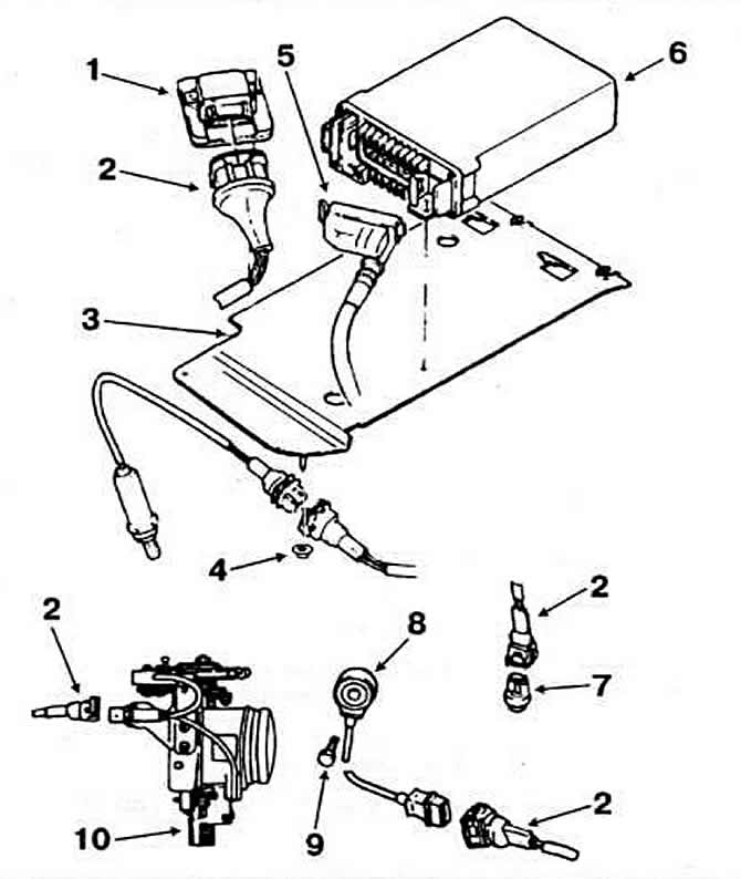
Pic. 2-120. Details of the subsystem for controlling the ignition timing of the KSUD «Digifant» vehicles with engine «PB»:
1 - switch;
2, 5 - connectors;
3 — controller mounting bracket;
4 - the place of connection of the oxygen content sensor in the exhaust gases (depending on configuration);
6 - controller;
7 - coolant temperature sensor;
8 - knock sensor;
9 - fixing bolt;
10 - idle throttle position sensor.
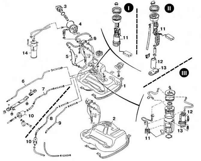
Pic. 2-121. Fuel system details:
I - cars with an engine «EZ»;
II - vehicles with an engine «RP»;
III - cars with engines «RV» and «2E».
1 - fuel tank of cars with a body «sedan»;
2 - fuel tank of cars with a body «station wagon»;
3 - fuel tank cap;
4 - sealant;
5 - expansion tank;
6 - fuel drain pipeline for cars with engines «RP» and «RV»;
7 - fuel supply pipeline for cars with engines «RP» and «RV»;
8 - fuel supply pipeline for cars with an engine «EZ»;
9 - fuel drain pipeline for vehicles with an engine «EZ»;
10 - fuel filter;
11 - fuel level sensor;
12 - fuel pump;
13 - mesh filter;
14 - adsorber on vehicles with engines «RP» and «RV».
Visitor comments