



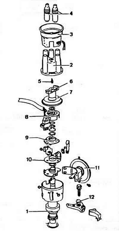
Fig. 2-46. Details of the ignition distributor sensor of the EZ and RP engines:
1 — distributor sensor housing;
2 — distributor sensor cover;
3 - interference suppression screen;
4 - interference suppression wire tips;
5 - central electrode;
6 — distributor rotor;
7 - protective screen;
8 - toothed anchor;
9 - wire cover;
10 - Hall sensor;
11 - vacuum regulator;
12 — locking bracket of the sensor-distributor housing.
The characteristics of the automatic ignition advance of the engine ignition distributor sensor regulators are shown in Fig. 2-45.
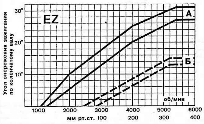
Fig. 2-45. Characteristics of automatic ignition advance of the EZ engine ignition distributor sensor regulators:
A - characteristic of a centrifugal regulator;
B — vacuum regulator characteristic. When checking the removed distributor sensor on the stand, divide the values indicated on the graph by two. When checking on the engine, add the value of the initial ignition advance angle.
Brand and catalog number of the Bosch switch 0 227 100 142.
Device. The ignition system contains a distributor sensor, an electronic switch and an ignition coil. The distributor sensor has the following main units: a contactless sensor, an ignition pulse distributor, centrifugal and vacuum ignition timing regulators. When the ignition timing regulators operate, the support plate rotates together with the sensor attached to it. When adjusting in the direction of ignition advance, the sensor rotates in the direction opposite to the direction of rotor rotation, and when adjusting in the direction of retardation, it rotates in the opposite direction.
The pulses generated by the sensor control the operation of the commutator, which functions as a breaker in the contact ignition system. In addition, the commutator ensures regulation of the current flow time in the primary circuit of the ignition coil according to a given law as a function of the engine speed and the voltage of the on-board network; limits voltage pulses in the primary circuit of the ignition coil; limits the primary circuit current when it reaches its maximum value; interrupts the primary current when the ignition switch contacts are closed and the engine is not running. It also contains a switch protection unit against network overvoltages.
Operating principle.The ignition system uses a contactless semiconductor sensor. The operation of these sensors is based on the use of the galvanomagnetic Hall effect. This effect is observed in the Hall element, which is a thin plate with four electrodes (Fig. 2-47). made of a semiconductor material. If a current passes through such a plate in the direction AB and a magnetic field acts on it at the same time, the direction of action of which H is perpendicular to the plane of the plate, then an emf of Hall arises on the faces F and E parallel to the direction of the current.
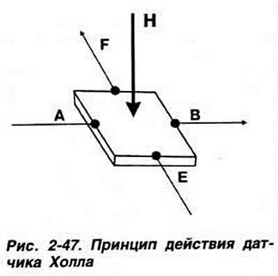
Since the signal from the Hall element is small, it depends on the supply voltage and temperature. semiconductor sensor (hall sensor) contains, in addition to the Hall element, a voltage stabilizer, an amplifier, a temperature compensation circuit, a signal generator and an output transistor. All elements are located in one microcircuit.
In the distributor sensor, the Hall sensor is located at a small distance from the permanent magnet, and a shutter with slits of a given width moves in the gap between them (Fig. 2-48). As a result, rectangular pulses come from the sensor, which control the operation of the ignition system. The width of the part of the shutter "b" that covers the magnetic field corresponds to the angle of the closed state of the breaker contacts. When passing through the gap, the switch closes the primary circuit of the ignition coil and the primary current flows through it. The primary current is interrupted at the moment the gap is covered, which causes a sharp decrease in the current and magnetic flux. The change in magnetic flux ensures the appearance of high voltage in the secondary winding.
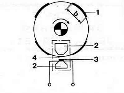
Fig. 2-48. Schematic diagram of the Hall sensor:
1 - curtain with slits
2 - permanent magnet
3 - Hall sensor
4 — gap
Ignition systems with a Hall sensor provide regulation of the energy accumulation time in the ignition coil depending on the engine speed and the voltage of the on-board network. Due to this, the spark discharge energy is increased in comparison with other systems by 1.5-2 times and reaches 50 mJ. This ensures the engine operation on very lean working mixtures and, as a result, a decrease in fuel consumption.
Warning: To avoid injury and damage to the electronic components of the ignition system, the following rules must be observed.
1. Connect and disconnect ignition system wires only when the ignition system power supply is disconnected.
2. Replace the ignition coil only with the specified type. Do not connect the capacitor to terminal "1" of the ignition coil (or switch).
3. If it is necessary to turn the crankshaft with the starter without starting the engine (for example, when checking compression in cylinders) disconnect the high-voltage wire from the central terminal of the ignition distributor sensor and connect it to a metal part of the engine that has a reliable connection to the negative terminal of the battery.
4. When starting the engine from an additional power source, its voltage should not exceed 16.5 V, and the connection duration should not exceed 1 min.
5. Wash the car only with the ignition system power disconnected.
6. When performing electric welding work on a vehicle, disconnect the wires from the battery terminals.
7. When towing a vehicle with a faulty ignition system, disconnect the wires from the ignition switch.
Visitor comments