
General instructions for the ignition system
The engine control unit -J623- is equipped with a self-diagnosis function. A voltage of at least 11.5 V is required to ensure that the electrical components function correctly. During certain checks, the engine control unit -J623- can detect and store a fault. Therefore, at the end of all checks and repair work, it is necessary to interrogate the fault memory and delete any errors that may have been stored in it.
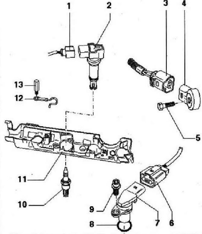
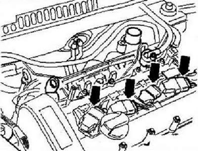
- 1 - Connector, black, 4-pin, unlock with assembly tool -T10118-
- 2 - Ignition coil 3 with output stage -N291-. Ignition coil 1 with output stage -N70-. Ignition coil 2 with output stage -N127-, Ignition coil 4 with output stage -N292-
- 3 - Connector, black, 2-pin, for knock sensor 1 -G61- connector pins are gold-plated
- 4 - Knock sensor 1 -G61- gold-plated connector contacts, remove compressor to remove
- 5 - 20 Nm. Tightening torque affects the operation of the knock sensor
- 6 - Connector, black, 3-pin, for Xonna-G40-sensor
- 7 - Hall sender -G40-
- 8 - O-ring, replace if damaged
- 9 - 10 Nm
- 10 - Spark plug, 30 Nm, remove and install with a spark plug wrench -3122 V-
- 11 - Wiring box, screw to the camshaft housing with a torque of 5 Nm
- 12 - Mass wire. Unscrew and screw only when the ignition is off
- 13 - 10 Nm. Unscrew and screw only when the ignition is off
Removal and installation of ignition coils with output stages
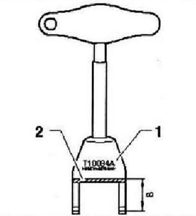
Note: Ignition coil housings with power output stages have been modified. Therefore, these ignition coils can only be removed and installed using puller -T10094 A-. The previously used puller -T10094- can still be used if modified as described below. Using suitable equipment, remove the metal in the marked area -2- to obtain a new nominal dimension -B- 18 mm. Add the letter A to the tool designation.
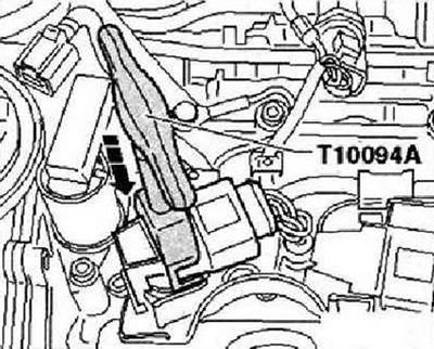
Fit puller -T10094 A- to ignition coil with output stage -arrow-.
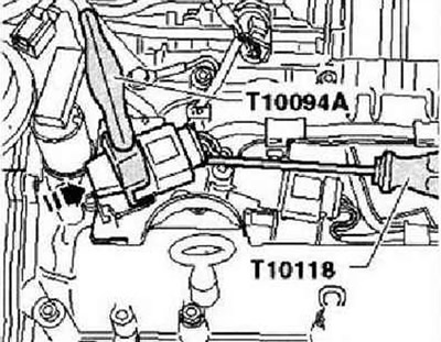
Slightly pull out the ignition coil with the output stage. Position assembly tool -T10118- as shown. Carefully loosen the connector lock and disconnect the connector.
Installation
Install puller -T10094 A- on ignition coil with final stage. Push the connector onto the ignition coil with the output stage until it snaps into place. Press ignition coil with output stage in direction -arrow- into cylinder head.
Security measures
To avoid personal injury and/or damage to the injection and ignition system, the following must be observed. Do not touch or disconnect high voltage wires while the engine is running and at starting speed. Disconnection and connection of electrical cables of the injection and ignition system, as well as measuring instruments, is only allowed when the ignition is switched off. If the engine is supposed to be cranked at starting speed without starting it. Disconnect 4-pin connector -arrows- from ignition coils with output stages.
Remove fuse for fuel pump control unit -J538- from fuse holder.
Welding data, spark plugs
| Engine code | BWK |
| The order of operation of the cylinders | 1-3-4-2 |
| Spark plug | |
| VW Part No | 101 905 626 |
| Distance between electrodes | 0.8...0.9 mm |
| Torque | 25 Nm |
Visitor comments