
Intake manifold
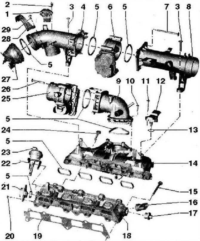
- 1 - Intake air temperature sender 3 -G520- with intake manifold pressure sender 3 -G583-
- 2 - 5 Nm
- 3 - 7 Nm, self-tapping screw. Tighten the fastening screw with a screwdriver only if the rotational speed of the screwdriver does not exceed 500 rpm. and the tightening torque is not more than 7 Nm
- 4 - Suction pipe
- 5 - Shaft seal, replace
- 6 - Regulating flap control unit -J808-. When replacing, delete values in memory and readjust engine control unit -J623-
- 7 - 7 Nm, self-tapping screw
- 8 - Suction pipe
- 9 - Intake manifold pipe
- 10 - 7 Nm, self-tapping screw
- 11 - 5 Nm
- 12 - Intake manifold pressure sender -G71-
- 13 - O-ring, replace
- 14 - Intake manifold. To remove - Removing and installing control flap control unit -J808- and throttle flap control unit -J338-
- 15 - 20 Nm
- 16 - Fuel pressure sender -G247-, 22 Nm. Check fuel pressure in high pressure area
- 17 - 80 Nm
- 18 - The lower part of the intake manifold. To remove - Removing and installing control flap control unit -J808- and intake manifold throttle flap control unit. To remove, dismantle the compressor. When replacing, delete adaptation parameters and adapt intake manifold flap potentiometer -G336- to engine control unit -J623-. Before removing and installing, fix the actuating element of the vacuum booster with a drill with a diameter of 2.5 mm. After installing the new intake manifold lower section, remove the vacuum booster actuator bracket. After installation, check the operation of the intake manifold flap using the manual vacuum pump -VAS 6213
- 19 - Seal, replace, observe installation position
- 20 - 2.2 Nm
- 21 - Intake manifold flap potentiometer -G336-. When replacing, delete values in memory and readjust engine control unit -J623-
- 22 - 2.2 Nm
- 23 - Vacuum actuator for intake manifold flap
- 24 - 20 Nm
- 25 - Throttle valve control unit -J338-. When replacing, delete values in memory and readjust engine control unit -J623-
- 26 - 7 Nm
- 27 - Pressure pipe from the turbocharger
- 28 - Clamp
- 29 -7 Nm
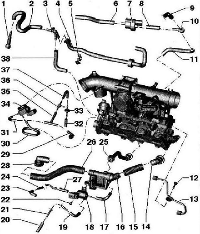
- 1 - Connecting fitting for the fuel supply line
- 2 - Fuel hose for the fuel supply line, fasten with spring clamps, check the fastening
- 3 - Connecting tube
- 4 - Fuel hose. Low pressure, to high pressure pump
- 5 - Mounting clamp
- 6 - Connecting hose to activated charcoal filter solenoid valve 1 -N80-
- 7 - Solenoid valve 1 for activated charcoal filter -N80-
- 8 - Connecting hose
- 9 - To pressure pipe
- 10 - Connecting tube
- 11 - Connecting hose to the intake manifold
- 12 - 8 Nm
- 13 - Fuel line. High pressure. Tightening torque for union nuts: 18 Nm
- 14 - Connecting fitting to the suction pipe
- 15 - Connecting hose
- 16 - Check valve for crankcase ventilation
- 17 - Connecting hose
- 18 - Charge air pressure control solenoid valve -N75-
- 19 - Connecting hose
- 20 - Connecting hose to turbocharger
- 21 - Connecting fitting -22- 5 Nm
- 23 - Connecting hose to turbocharger
- 24 - Connecting fitting
- 25 - Connecting fitting for crankcase ventilation
- 26 - Connecting hose for crankcase ventilation
- 27 Connecting hose to charge pressure control solenoid valve -N75-
- 28 - Connecting fitting for crankcase ventilation, connected to the regulator body
- 29 - Vacuum hose from the vacuum receiver
- 30 - Vacuum hose to the vacuum drive
- 31 - Vacuum hose to intake manifold flap valve -N316-
- 32 - Vacuum hose to intake manifold
- 33 - Filters
- 34 - Intake manifold flap valve -N316-
- 35 - Connecting fitting for vacuum lines
- 36 - Connecting fitting
- 37 - Vacuum hose to intake manifold
- 38 - Fuel hose to the bottom of the intake manifold, for fuel recirculation
Fuel rail with injectors
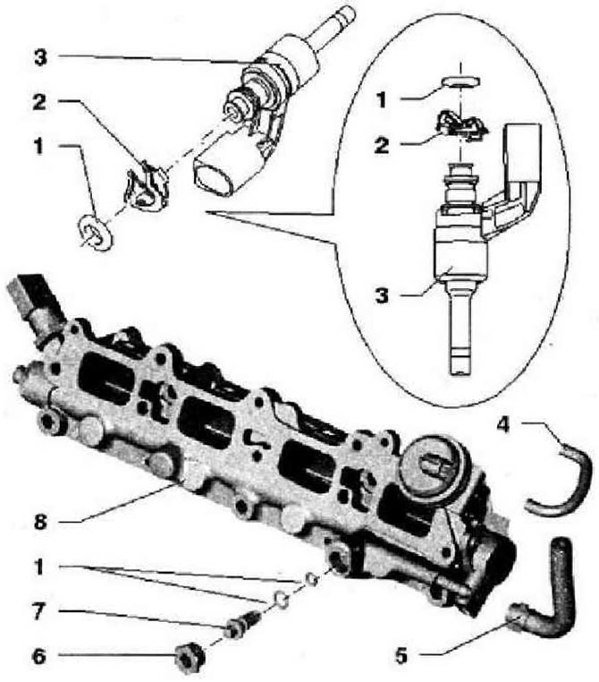
- 1 - O-ring, replace, moisten lightly with clean engine oil before installation
- 2 - Spring element, after each removal, replace the lower part of the intake manifold, pay attention to the correct attachment to the injector
- 3 - Injector for cylinder 4 -N33-. Cylinder 1 injector -N30-. Cylinder 2 injector -N31-. Cylinder 3 injector -N32-. With teflon o-ring and support washer, after removing the injector, the teflon o-ring and washer must be replaced
- 4 - Vacuum hose
- 5 - Drain fuel line from the high pressure pump, Blue color or blue marking, fasten with spring and clamps, check the fastening
- 6 - 20 Nm
- 7 - Reducing valve, replace the dismantled valve, lightly moisten the O-rings with clean engine oil before installing, press in with an Allen key 8 mm by hand
- 8 - The lower part of the intake manifold. To remove - Removing and installing control flap control unit -J808- and intake manifold throttle flap control unit. To remove, dismantle the compressor
Air filter
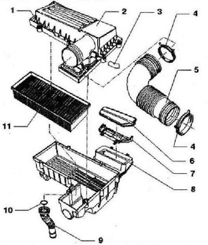
- 1 - 1.6 Nm
- 2 - Upper part of the air filter housing
- 3 - Vacuum hose. Do not use tools with sharp edges to remove hoses to prevent damage to the nozzle and vacuum hose, replace if damaged, from the camshaft housing
- 4 - Spring clamp
- 5 - Air intake sleeve
- 6 - Lid
- 7 - Intake air duct
- 8 - Lower part of the air filter housing with captive mounting bolt, 8 Nm, with suction pipe
- 9 - Water drain pipe. When installing, the arrows on the bottom of the air filter housing and on the water drain pipe must be opposite each other
- 10 - O-ring, replace
- 11 - Filter insert
Visitor comments