



Contents: Removal ↓ Installation ↓
Removal
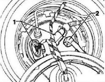
With the ignition off, disconnect the battery ground wire. Unscrew the fuel filler cap assembly mounting bolt and remove it. Pump out the fuel from the tank and clean the surface near the filler pipe. Remove the bench seat. Remove the cover from the fuel delivery module. Remove connector "1" and fuel line "2" from the right (depending on the direction of travel) flange.
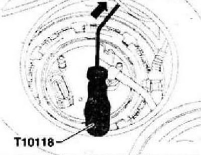
Release the connector "arrow" on the fuel pump control unit -J538- using the installation tool "T10118" and remove the connector.
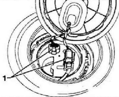
Remove connector "1" from the left (depending on the direction of travel) flange.
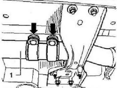
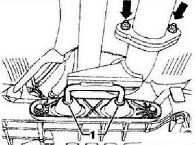
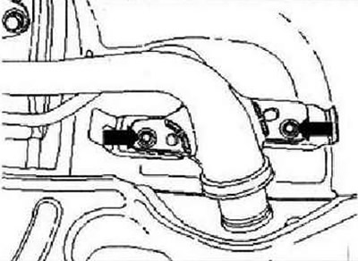
Unscrew the nuts of the double clamp "arrows" and move it forward along the exhaust pipe "1".
Unscrew the nuts "arrows" and pull the exhaust pipe back. Remove the rear part of the exhaust system with the middle and rear muffler.
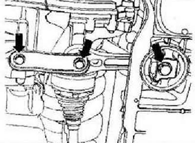
Unscrew the rocking support "arrows". Remove the cardan shaft.
CAUTION: The fuel in the pressure line is under pressure!
Disconnect the fuel line "1" (black) and the ventilation line "2" (white) at the junction. If independent heating is installed, also remove the fuel line "3".
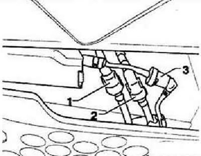
Instructions: To disconnect the fuel lines, press the retaining ring.
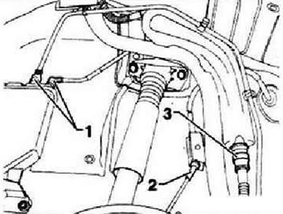
Unscrew the right rear wheel. Remove the rear right mudguard. Disconnect the ventilation pipes "1" from the activated carbon canister and the filler neck "3". Disconnect the cable "2" from the holder. Remove the hatch and the filler cap of the fuel tank. Disconnect the ground wire on the filler neck.
Unscrew the fuel tank neck from the Strelka body.
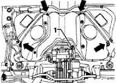
Unscrew the fastening bolt "1". Unscrew the bandage and the fastening bolts "arrows". Support the fuel tank with the tilting device -VAG 1383 A-.
Installation
With the help of a second mechanic, pass the filler neck between the rear axle and the body. Then place the fuel tank on the tilting device -VAG 1383 A-. Slowly lift the fuel tank to the installation position and secure it.
Instructions: Only bolts with loose washers are allowed to be used to secure the fuel tank clamps. Using other screws may cause the clamps to twist when tightened.
Tighten the new clamp mounting bolts "arrows" and the new screw "1" to 20 Nm + 90°. Tighten the coolant pump mounting bolts "arrows" to 8 Nm + 90°. Further installation is carried out in the reverse order of removal. In this case, the following must be taken into account. The ventilation and fuel lines must be laid without kinks. Check for a tank/body ground connection on the filler pipe. Ensure proper fastening of the fuel hoses. After installing the fuel tank, check whether the feed and ventilation lines are still secured to the fuel tank.
Visitor comments