
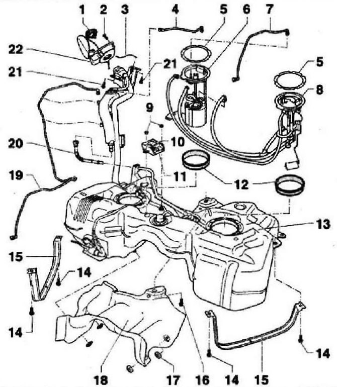
- 1 - Cover, replace if damaged
- 2 - Fixing bolt
- 3 - Earth connection, check the security of fastening
- 4 - Ventilation line to the absorber, check the reliability of fastening
- 5 - Union nut, 110 Nm, check the tightness. Remove and install with fuel level sender wrench -30876 - Fuel delivery module, install in the correct position on the tank, with fuel level sender -G-, clean screen if dirty
- 7 - Pressure line, black, clipped on the side of the fuel tank, check the fastening
- 8 - Fuel level sender 2 -G169- with jet pump
- 9 - 3.5 Nm
- 10 - Bracket for fuel pump control unit -J538-
- 11 - Fuel pump control unit -J538-
- 12 - O-ring, if damaged, replace, install dry in the opening of the fuel tank, moisten with fuel when installing the flange
- 13 - Fuel tank
- 14 - 20 Nm and tighten by 90°, replace. Only bolts with loose washers may be used to fasten the fuel tank clamps. If other screws are used, the tie-down straps may twist when tightened
- 15 - Clamp, note installation position
- 16 - 20 Nm and tighten by 90°, replace
- 17- Clamping washer
- 18 - Heat shield
- 19 - Ventilation line, clipped to the side of the fuel tank, check the fastening
- 20 - Ventilation line, check the security of fastening
- 21 - 8 Nm and tighten by 90°, replace
- 22 - Filler cap, with rubber container
Installation position of flanges for fuel delivery unit and fuel gauge sender 2 -G169-
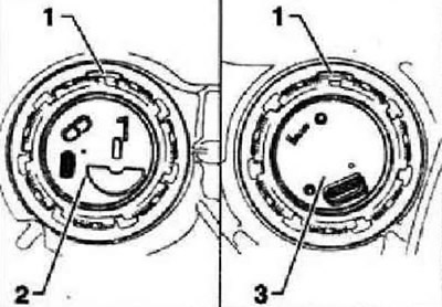
Fuel supply module -3-: shackle -1- points in direction of travel.
Fuel gauge sender 2 -G169-2-: eyelet -1- faces direction of travel.
Instructions: Disregard the arrows on the circlips.
Visitor comments