
English Русский
Български
Беларускі
Український
Српски
Hrvatski
Română
Polski
Slovenský
Magyar
  |  Articles  |  Sitemap  |  Contacts  |    |
Car maintenance Ford Car maintenance Hyundai Car maintenance Chevrolet Car maintenance BMW Car maintenance Audi Car maintenance Opel Car maintenance AvtoVAZ
VWmanual.ru


Main   Passat   Golf   Polo   Touareg   Tiguan   Sharan   Transporter   Others  
Tiguan 1 (2007-2015)

Removal and installation of lubrication system elements (VW Tiguan 1)

  • Main
  • Tiguan
  • Tiguan 1
  • Power unit
  • Petrol engine 1.4 BWK
  • Removal and installation of lubrication system elements
            0


Instructions: If large quantities of metal shavings are found in the engine during repair, this may be due to a faulty connecting rod bearing. To avoid subsequent damage, the following must be done after repair: thoroughly clean the lubrication channels, replace the oil filter. The oil level must not exceed the max mark - risk of damage to the catalyst!


The amount of oil to be filled with an oil filter is 4.0 l.
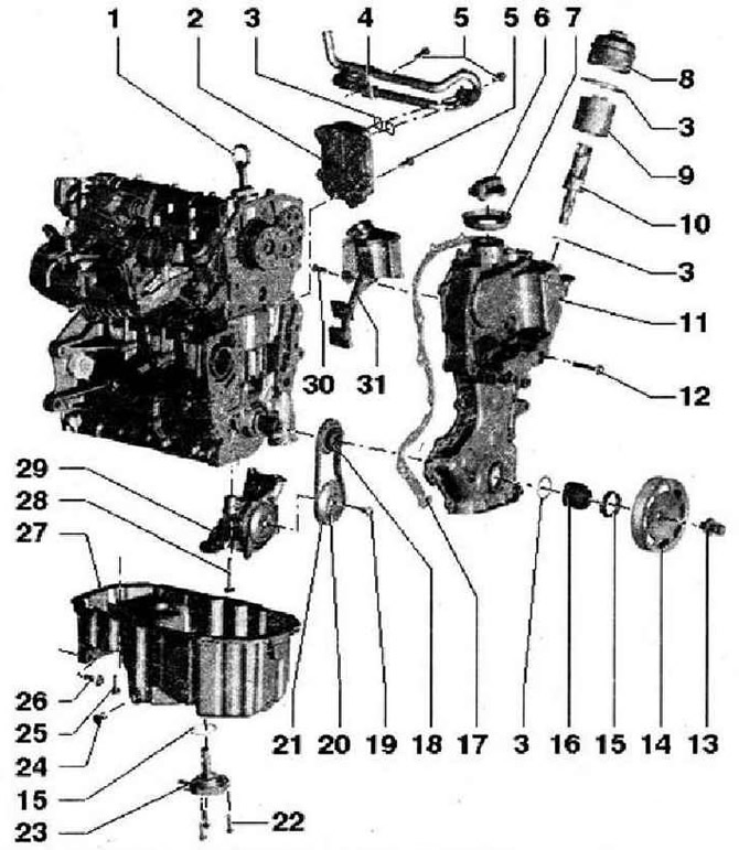
The amount of oil to be filled with an oil filter is 4.0 l.

  • 1 - Oil dipstick. The oil level must not exceed the max mark!
  • 2 - Oil cooler
  • 3 - O-ring, replace
  • 4 - Cooling system pipe for oil cooler, tightening torque of bracket to engine crankcase: 20 Nm
  • 5 - 8 Nm
  • 6 - Cover, replace gasket if damaged
  • 7 - Lip seal, replace if damaged
  • 8 - Oil filter housing cover, 25 Nm. With quick-closing valve, opening pressure: 2.50 bar overpressure. With oil return shut-off valve
  • 9 - Filter insert
  • 10 - Valve
  • 11 - Timing gear cover. Additionally install using sealant D 176 501 A1. To facilitate installation, screw in two M6x80 spacer bolts into the camshaft housing and cylinder block. To facilitate installation of the timing gear cover, screw in the oil pan with two bolts
  • 12 - 10 Nm
  • 13 - Fastening screw. There should be no oil or grease on the contact surface of the bolt head. Insert, having lubricated with oil (thread), fix the belt pulley from turning with the help of counter support 3415. The tightening angle can be measured with a standard measuring disc, eg Hazet 6690
  • 14 - Belt pulley. There should be no oil or grease on the mating surfaces, fix the belt pulley from turning using the counter support "3415"
  • 15 - Lip seal, replace
  • 16 - Bearing bushing. There should be no oil or grease on the mating surfaces of the bearing bushing
  • 17 - Seal, replace if damaged
  • 18 - Sprocket for oil pump drive
  • 19 - 20 Nm and turn 90°, replace
  • 20 - Oil pump sprocket, secure with locking key "T10172"
  • 21 - Oil pump drive chain, mark direction of movement before removing (installation position)
  • 22 - 10 Nm
  • 23 - Engine oil level and temperature sensor "G266", if damaged, replace, check
  • 24 - Oil drain plug, 30 Nm. With fixed lip seal, replace
  • 25 - 13 Nm. Loosen and tighten bolts only on the flywheel side using the "T10058" attachment
  • 26 - 45 Nm
  • 27 - Oil pan, clean the mounting surfaces before installation, install with silicone sealant D 176 600 A1
  • 28 - 25 Nm
  • 29 - Oil pump, replace only as an assembly
  • 30 - 5 Nm
  • 31 - Oil separator

Marks on the dipstick
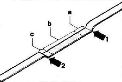


Marks on the dipstick


The original text can be found at: VWManual.ru


  • 1 - Mark max
  • 2 - Min mark
  • a - if the oil level is above the grooved field and below the max mark - do not add oil!
  • b - actual level in the shaded field: engine oil can be added c - at oil level from min mark to ribbed field: add max 0.5 l of oil!

This article is available at russian, bulgarian, belarusian, ukrainian, serbian, croatian, romanian, polish, slovak, hungarian
The text has been checked: Tarasov Ivan

Share information:

Previous articles
Engine assembly
Disassembling the engine
Engine installation
Removal the engine
Specifications of the 1.4 litre/110 kW petrol engine (BWK)
Car engine number
Next articles
Removal and installation of cooling system components
Draining and filling the coolant
Removal and installation the radiator and radiator fan V7
Removal and installation the cooling system pump
Relieving pressure in the high pressure area of the fuel system
Fuel tank device


Similar articles from other manuals for VW cars:
General information about the lubrication system Passat B3 (1988-1993)
Technical data of the cooling and lubrication system Golf 2 (1984-1993, petrol)
Lubrication system Polo 3 (1995-2003)
Removal and installation of lubrication system elements (petrol… Touareg 1 (2002-2006)
Engine lubrication system — design description Sharan 1 (1995-2000)
Engine lubrication system — design description Transporter T4 (1990-2003)
Elements of the lubrication system Caddy 3 (2003-2010)
Link to this page in different formats


Visitor comments


No comments yet


How much will 10 + 16 =


Tiguan 1 
  • General information
  • Characteristics
  • Vehicle overview
  • Power unit
  • Petrol engine 1.4 BWK
  • Petrol engine 1.4 CAVA
  • Engine 2.0 (petrol)
  • Engine 2.0 (diesel)
  • Transmission
  • 6-speed manual gearbox 0A6
  • 6-speed automatic gearbox 09M
  • Drive shafts
  • Chassis
  • Front suspension
  • Rear suspension (2x4)
  • Rear suspension (4x4)
  • Air suspension
  • Wheels and rims
  • Brake system
  • Steering gear
  • Body
  • External equipment
  • Internal equipment
  • Electrical equipment
  • Power devices
  • Appliances and lighting
  • Communication systems
  • Heating and air conditioning
  • Electrical circuits
VWmanual.ru © 2016-2026 | Mobile version | News and articles | Sitemap: EN BG BY UA RS HR RO PL SK HU | Write message | Site search
Passat B2 • Passat B3 • Passat B4 • Passat B5 • Passat B6 • Golf 1, diesel • Golf 1, petrol • Golf 2, petrol • Golf 2 • Golf 3 • Golf 4 • Golf 5 • Polo 3 • Polo 4 • Touareg 1 • Tiguan 1 • Sharan 1 • Transporter T3 • Transporter T4 • LT 28 • LT 2D • Beetle • Caddy 3 •
Our website uses cookies to ensure functionality and convenience.