
Instruction. If, during engine repair, metal chips and dust are found in engine oil in large quantities - the source of which is increased wear, for example, due to damage to the connecting rod bearing, then in order to avoid subsequent damage, it is necessary to replace the oil filter in addition to cleaning the lubrication channels. All seating and working surfaces must be lubricated before installation.
Belt drive
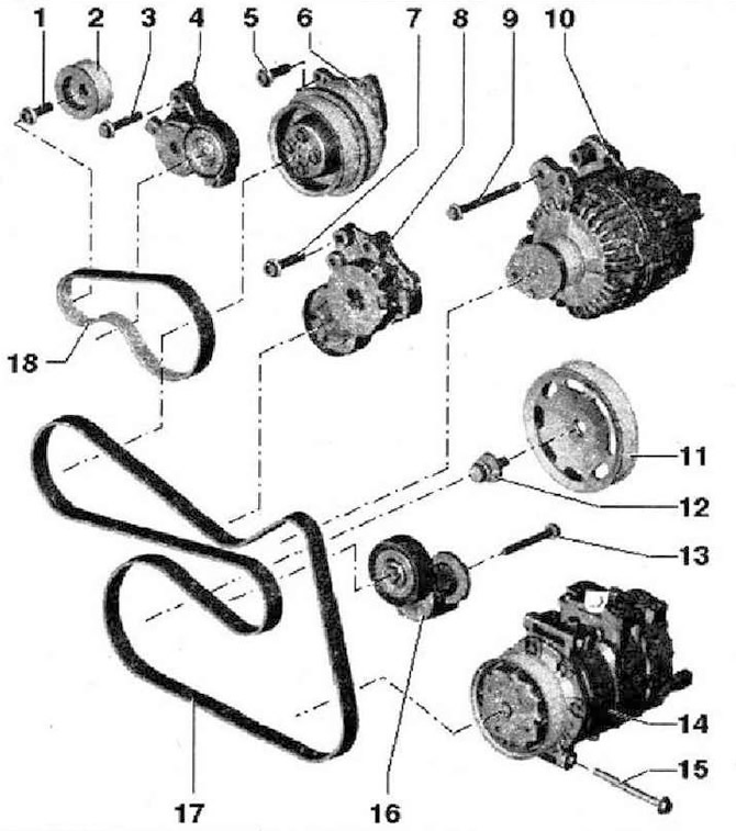
- 1 - 40 Nm and tighten by 90°. To loosen and tighten the mounting bolt, hold the compressor shaft with a wrench, replace
- 2 - Compressor belt pulley
- 3 - 23 Nm
- 4 - Tensioner for compressor V-ribbed belt, loosen with wrench, secure with locking pin -T10060 A-
- 5 - 8 Nm
- 6 - Coolant pump with magnetic compressor clutch -N421-
- 7 - 23 Nm
- 8 - Tensioner for V-ribbed belt, loosen with a SW 16 wrench -T10241-, secure with locking pin -TY060 A-. On vehicles with a manual gearbox, an overrunning pulley is installed instead of a tensioner. Mounting bolt tightening torque: 40 Nm
- 9 - 23 Nm
- 10 - Three-phase generator
- 11 - Belt pulley for the crankshaft. Mating surfaces must be free of oil and grease
- 12 - Mounting screw, replace. There must be no oil on the contact surface of the bolt head and grease should be inserted after lubricating with oil (carving), secure the belt pulley with the locking tool -3415-, tightening can be done in several steps. The tightening angle can be measured with a standard measuring disc, e.g. Hazet 6690
- 13 - 40 Nm and tighten by 90°, replace. Removal and installation in a raised vehicle
- 14 - Air conditioning compressor
- 15 - 25 Nm
- 16 - Tensioner for V-ribbed belt, loosen with a wrench, fix with a 4 mm Allen key
- 17 - V-ribbed belt, mark direction of travel before removing. When installing the V-ribbed belt, pay attention to the direction of travel and the correct fit on the pulleys and tensioners
- 18 - Compressor V-ribbed belt, mark direction of travel before removing. When installing the V-ribbed belt, pay attention to the direction of travel and the correct fit on the pulleys and tensioners
Cylinder block
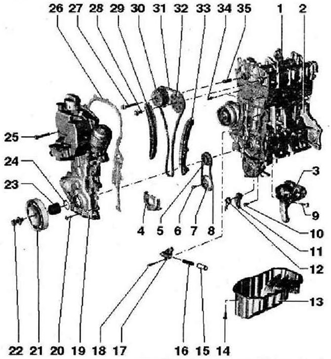
- 1 - cylinder head with camshaft housing. The adjacent surface must not be treated with integrated camshaft bearings remove the remnants of the old sealant before installation, apply AMV188 001 02. To install, insert vertically from above with dowel pins into the cylinder head bores
- 2 - Cylinder block
- 3 - Bracket for auxiliary units. For Tensioner and A/C Compressor
- 4 - Lid
- 5 - Asterisk for driving the oil pump and timing chain. Mating surfaces must be free of oil and grease
- 6 - 20 Nm and tighten by 90°, replace
- 7 - Asterisk. Secure sprocket with -T10172- locking key
- 8 - Drive chain, mark direction of travel before removing (installation position)
- 9 - 25 Nm
- 10 - 15 Nm
- 11 - Chain tensioner with strap for oil pump drive
- 12 - Spring
- 13 - Oil pan, clean seating surfaces before installation. Assemble with silicone sealant D 176 404 A2
- 14 - 15 Nm
- 15 - Piston for chain tensioner
- 16 - Spring
- 17 - Chain tensioner
- 18 - 9 Nm
- 19 - Timing mechanism cover. Additionally, install using sealant D 176 501 A1, to facilitate installation, screw two spacer bolts M6x80 into the camshaft housing and cylinder block. To facilitate the installation of the timing cover, screw the oil pan with two bolts
- 20 - 10 Nm
- 21 - Belt pulley, follow the tightening method. The mating surfaces must be free of oil and grease, secure the belt pulley against rotation using the locking tool -3415-
- 22 - Mounting screw, replace. The contact surface of the bolt head must be free of oil and grease, insert after lubricating with oil (carving). Secure the belt pulley against rotation using the locking tool -3415-, the tightening angle can be measured with a standard measuring disc, e.g. Hazet 6690
- 23 - Bearing sleeve. Mating surfaces must be free of oil and grease
- 24 - O-ring, replace
- 25 - 50 Nm
- 26 - Seal
- 27 - 40 Nm and tighten by 90°. Secure sprocket with locking key -T10172-. Bolt with left-hand thread, replace
- 28 - 50 Nm and tighten by 90°, replace
- 29 - Tensioner strap
- 30 - Phase shifter, disassembly prohibited
- 31 - Timing chain
- 32 - Asterisk for exhaust camshaft. Secure the sprocket with the locking key -T10172-
- 33 - Plank damper for the timing chain
- 34 - Guide bolt, 20 Nm
- 35 - Bearing sleeve
Removing the V-ribbed belt
Instructions: To remove the V-ribbed belt, loosen the two tensioners.
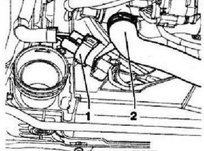
Drain coolant by removing hose -2-. Position -1- is ignored.
Unlock the clip and remove the right-hand connector in the direction of travel from the radiator. Depending on the vehicle's equipment, remove the noise insulation or the underride guard. Mark the running direction of the V-ribbed belt. To loosen the V-ribbed belt, turn the tensioning element from above using a SW16 wrench -T10241 -in the -direction of the arrow-.
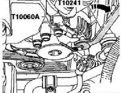
Secure tensioning element with locking pin -T10060 A-. To loosen the V-ribbed belt, turn the tensioner from below using a SW 16 wrench in -direction of the arrow-.
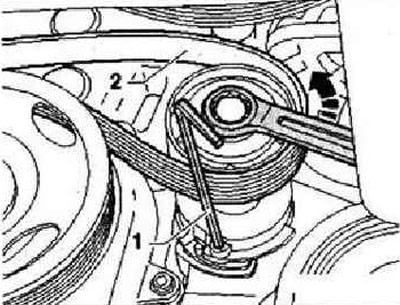
Secure the tensioning element with a 4 mm Allen key -1-. Remove poly V-belt -2-.
Visitor comments