



The engine has an overhead camshaft. The camshaft is driven by a toothed belt. The cylinder block is cast iron, the cylinder head is aluminum.
Compared to the diesel engines that were installed previously, it has several design changes:
- the cylinder head, valve seats, valves and combustion chambers are made of materials that can withstand higher temperatures;
- special nozzles (injectors) spray oil onto the lower part of the pistons, cooling them;
- the piston design has been changed;
- the front end of the crankshaft is modified;
- the oil cooler is located between the oil filter and the filter flange;
- due to the installation of a turbocharger, the exhaust system and intake system were modified.
Caution! All diesel engines are very sensitive to dirt, so when performing any work on the engine, make sure that dirt or other foreign bodies do not get into the openings of the pipes and their connections. It is best to immediately seal all fuel pipes, hoses and other openings with adhesive tape. Disassembling the engine is described in detail in subsections 17.3-17.10. Thus, we can consider the work that can be carried out either on an installed engine or on a removed one, without describing any engine disassembly operation twice. If a complete disassembly of the engine is carried out, then simply combine the individual operations with each other in the specified sequence. When disassembling, mark the location of all removable parts and components so that they can be installed in their original position during assembly, in the event that they are reused. This is especially important for pistons, valves, covers and bearing shells. Arrange the parts in such a way as to not mix them up.
Caution! Do not mark bearings and seals by scratching their surface or punching. Many of the parts are made of light alloy and therefore must be handled with care. If a hammer must be used to remove any part, it may only be a rubber, plastic or leather-covered hammer.
If possible, install the engine on a suitable mounting stand. When disassembling the engine, proceed in the following sequence:
- remove the drive shaft thrust bearing bracket and the turbocharger;
- drain the engine oil.
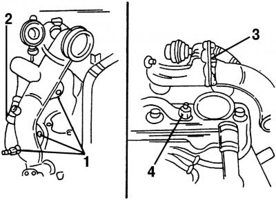
Fig. 374. When carrying out any disassembly work, disconnect: 1 - intake pipe mounting bolts; 2 - air hose from turbocharger; 3 - air supply hose from the intake system; 4 - crankcase ventilation hose
Remove the following parts from the engine, referring to Fig. 374:
- unscrew bolts 1 and disconnect the inlet pipe from the turbocharger;
- disconnect air hose 2 from turbocharger and charge air radiator;
- disconnect the charge air hose from the intake system 3;
- disconnect the crankcase ventilation hose 4 from the oil filter.
Disconnect the coolant line and remove the coolant hose from the bracket and oil cooler.
Remove the hose clamp from the flywheel side and disconnect the coolant line.
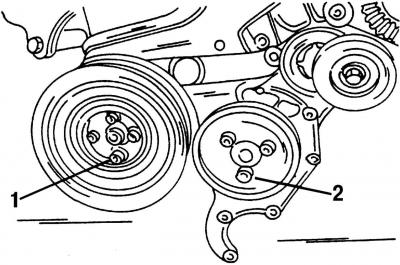
Fig. 375. Remove the crankshaft vibration damper 1 and the power steering pump pulley 2. The power steering pump pulley can be secured in a stationary position using a hex key
Remove the crankshaft pulley (4 bolts) and the power steering pump pulley (Fig. 375) located at the front of the engine.
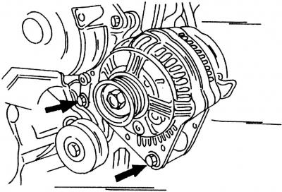
Fig. 376. Generator mount. The V-belt tensioner is visible from below
Remove the generator (Fig. 376).
Loosen the four bolts securing the engine mount clamp and remove it.
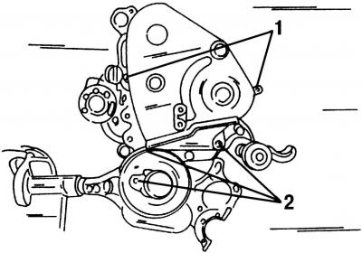
Fig. 377. Fastening the poly V-belt protective covers: 1 - top cover; 2 - bottom cover
Remove the upper cover of the poly V-belt. It is secured with spring clamps 1 (Fig. 377). Unscrew the lower cover. It is secured with three bolts 2.
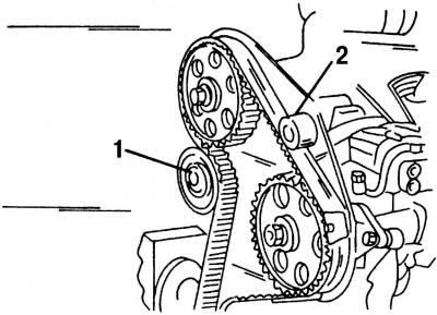
Fig. 378. Removing the poly V-belt: 1 - Timing belt tension roller; 2 - toothed drive belt guide roller
Remove the poly V-belt. If you plan to reinstall the old belt, mark the direction of rotation of the poly V-belt by applying a color mark on its surface. Loosen the nut and press the tension roller 1 (Fig. 378) to the side. Remove the guide roller 2. Remove the toothed belt. Remove the belt tensioner.
Remove the cylinder head cover. Disconnect the crankcase ventilation hose from the lower connection and leave it on the cylinder head cover. Remove the protective caps located above the cylinder head cover mounting nuts, unscrew the nuts and remove the cover.
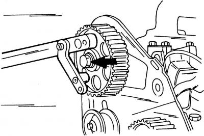
Fig. 379. Method of fixing the camshaft gear
Fix the camshaft pulley in a stationary position, remove it. The stop intended for this is shown in Fig. 379. It is impossible to use a puller for this operation, you can insert a mandrel through the hole in the metal wall located behind the wheel and knock the pulley in a circle.
Remove the fuel injection pump gear. It should be removed using a special three-pin puller, the teeth of which should be inserted into the holes on the pump gear. First, unscrew the gear nut. To fix the gear in a stationary position, insert a mandrel into the hole on the pump gear and hold it, resting the mandrel against the cylinder block.
Unscrew the two bolts on the cylinder head and the bolt on the fuel injection pump and remove the inner protection of the poly V-belt.
Remove the engine oil dipstick.
Disconnect the fuel shut-off valve wire end from the injection control solenoid valve.
Unscrew the high-pressure fuel lines from the injectors and the high-pressure fuel pump. They are secured with union nuts.
Remove the fuel injection pump. To do this, unscrew the two nuts on one side and the bolt with the nut on the other side.
After this, disconnect the various wires and hoses. They are shown in Figure 380:
- disconnect the plug connector of the oil pressure switch 1;
- disconnect the temperature sensor 2 connector;
- remove the plug connector of the crankshaft position sensor 3 from the bracket;
- disconnect the connector block of the needle lift sensor 4 from the holder;
- disconnect coolant hose 5 from the cylinder head distribution chamber.
Unscrew the glow plug electrical busbar and disconnect the oil drain hoses.
Loosen the injector fasteners and remove the injectors from the cylinder head.
Remove the glow plugs.
Disconnect the coolant temperature sensor connector.
Loosen the hollow bolt, ring joint, union nut on the turbocharger located near the turbocharger and unscrew the connection. Disconnect the plug connector of the additional heater, remove the wiring harness on the engine and unscrew the connecting pipe for EGR (4 bolts).
Remove the exhaust pipe and turbocharger. First, loosen the hollow bolt of the oil pipe ring joint, then unscrew the exhaust pipe heat shield (2 bolts), and then unscrew the 8 exhaust pipe mounting bolts.
Unscrew the 6 exhaust manifold mounting bolts and remove it.
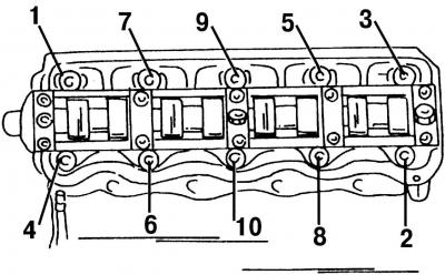
Fig. 382. The order of unscrewing the cylinder head bolts. When installing the cylinder head, tighten the bolts in the reverse order
Loosen the cylinder head mounting bolts evenly in the reverse order relative to the bolt tightening sequence (Fig. 382) and remove them. To loosen the bolts, you need a special Allen key, without which you can damage the inner part of the hexagonal head of the bolts, so that it will no longer be possible to unscrew them. Remove the cylinder head gasket.
Attention! The bolts are not suitable for reuse and must be replaced with new ones.
Remove the accessory mounting bracket and oil filter.
Unscrew the fuel injection pump mounting bracket (3 bolts) and remove the oil cooler (one nut, in the center).
Remove the three bolts in the oil filter base and remove the oil filter base. Remove the vacuum pump tension plate and remove the pump.
Remove the components installed on the left side of the engine: crankcase ventilation connection (2 bolts), crankshaft position sensor (1 bolt, 1 spring clip) and a dipstick for measuring the oil level in the engine.
Fix the crankshaft in a stationary position by inserting a screwdriver into the toothed crown. Unscrew the 6 clutch mounting bolts evenly crosswise so that they can be removed. Then completely remove the clutch.
Remove the crankshaft and intermediate shaft gears from the front side of the engine. Secure the crankshaft and intermediate shaft in a stationary position.
Fix the flywheel in a stationary position and unscrew the 6 bolts that secure it.
Unscrew the engine intermediate plate.
Turn the engine over and unscrew the oil pan (20 bolts). Remove the gasket.
Unscrew the oil pump located at the bottom of the crankcase and remove it.
Remove the six bolts and the rear flange of the sealing ring. Remove the gasket.
Attention! The flange is not suitable for reuse and must be replaced with a new one.
Unscrew the crankshaft oil seal flange from the front side of the engine. Remove the gasket. Knock out the oil seal.
Unscrew the intermediate shaft flange and press the flange. There is a sealing ring under the flange. Remove the shaft from the engine.
Turn the crankshaft so that the two connecting rods are at the bottom dead center. Mark the connecting rod bearing caps with the cylinder numbers (in color) and unscrew the bearing caps one by one. Remove the connecting rods together with the pistons in an upward direction from the cylinder bore one by one. Make sure that the bearing shells and bearing caps are immediately attached to the corresponding connecting rods.
Remove the crankshaft. The bearing caps in this case are marked with numbers (No. 1 - on the pulley side, No.5 - on the flywheel side). See subsection 17.9.
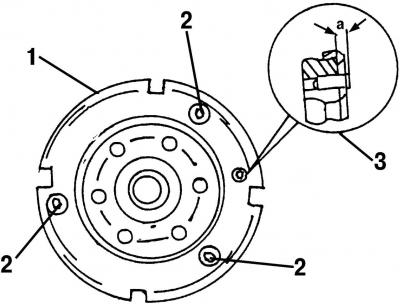
Fig. 383. Flywheel: 1 - toothed rim; 2 - toothed rim mounting bolts; 3 - Set screw (must protrude a distance a)
Unscrew the toothed rim, which serves to determine the crankshaft speed, from the nose of the crankshaft. Fig. 383 shows the method of its attachment.
Remove the oil jets from the bottom of the crankcase (unscrew the bolts).
Visitor comments