



- generously lubricate the valve stems with engine oil and insert them into the corresponding guide bushings;
- install the lower valve plates;
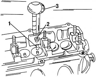
Fig. 405. Installing oil deflector caps: 1 - plastic sleeve; 2 - oil deflector cap; 3 special tool 10-204
- using special tool 10-204 (Fig. 405), install the oil deflector caps;
- place the plastic sleeve 1 of the special tool onto the protruding part of the valve guide sleeve. The plastic sleeve protects the new valve stem seals from damage that they may receive when they come into contact with sharp recesses on the valve stems;
- lubricate the oil seal 2 well and place it on the plastic sleeve;
- place tool 3 on the valve stem seal and carefully press it into the guide bushing. Remember that installing the valve stem seals without this special tool or a similar tool can damage them, which will result in increased oil consumption. As a last resort, you can use a piece of pipe of a suitable diameter, but be extremely careful not to damage the valve stem seals or the spring rings.
If the valves have been lapped, each valve must be installed in the seat to which it was lapped.
Install one inner and one outer spring for the corresponding valve into the cylinder head (if old springs are installed) install them using a valve puller.
Use a plastic hammer to hit the top of the valve stem. This will cause the incorrectly installed valve stem halves to fly out of their sockets. To avoid losing them, place a rag around the ends of the springs.
Insert the pushers into the holes according to the marks (having previously greased them well), if old pushers are used.
Generously lubricate the camshaft with oil in the bearing areas.
Install the camshafts in the housings and turn them several times. Install the shafts so that both cams of the first cylinder on the two shafts are facing upwards.
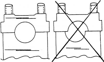
Fig. 406. When installing the camshaft bearing caps, be sure to ensure that they are positioned correctly
Bearing caps should only be installed as shown in Fig. 406 and only in accordance with the method described below so that the camshaft is not deformed.
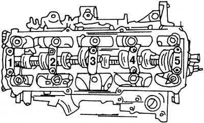
Fig. 407. Numbering of camshaft bearing caps. Caps are installed in the specified sequence
Using Fig. 407, put on bearing caps No.2 and No.4 and hand-tighten the nuts. Since the bearing caps are offset, check to see if they are seated correctly. To do this, using Fig. 406, determine if the caps were put on correctly.
Tighten the nuts of the installed bearing caps alternately and crosswise in several passes to a tightening torque of 20 N·m. Make sure that the surface of the caps is located opposite the surface of the cylinder head.
Fit caps No.5, 1 and 3. Tighten the nuts alternately and crosswise in several stages to a tightening torque of 20 N·m. The numbering of the bearing caps corresponds to the numbering shown in Fig. 407. This figure should be used as a guide when installing the camshaft.
Take the camshaft oil seal and see which side the spring is on. The side with the spring should be facing inward. Lubricate the sealing surface and the rolling surface of the camshaft. To install a new oil seal, you can use a pipe of the appropriate diameter. The pipe should completely match the size of the outer part of the oil seal. Push the oil seal straight on and hit it until its outer surface goes completely inward. You can install the oil seal in the same way as described for installing the front crankshaft oil seal.
Install the timing pulley onto the camshaft (don't forget about the wedge) and tighten the bolt with the washer. Keeping the camshaft stationary (for example, using an old toothed drive belt) tighten the bolt to 45 Nm.
Install the intake pipe and exhaust manifold onto the cylinder head (use new gaskets).
Install four injectors and glow plugs.
Install all removed parts.
Visitor comments