



Remove the ground wire terminal from the battery.
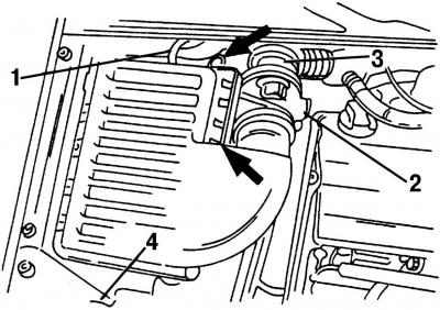
Fig. 390. To remove the air filter, disconnect: 1 - hose going to the vacuum regulator of the EGR system; 2 - mass air flow sensor; 3 - air intake; 4 - inlet hose
Remove the air filter as described (Fig. 390).
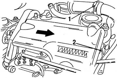
Fig. 391. Removing the engine cover: 1 - air supply hose; 2 - plug
Remove the engine cover and the air intake hose. Remove plug 2 (Fig. 391) and the spring clip. Press the cover in the direction of the arrow to the side and disconnect air intake hose 1 from the intake manifold.
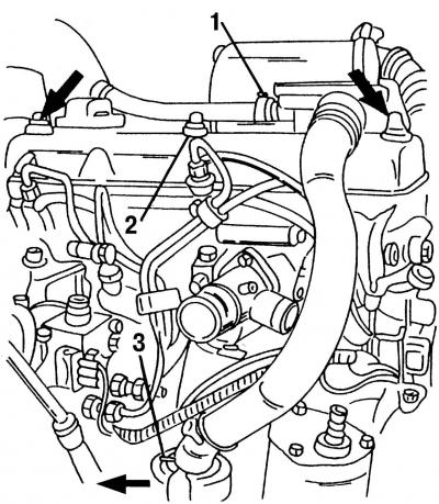
Fig. 392. Removing the cylinder head cover: 1 - hose; 2 - safety caps; 3 - spring clamp
Remove the cylinder head cover (the crankcase ventilation housing remains on the cylinder head). Disconnect hose 1 (Fig. 392) from the cylinder block cover, loosen spring clamp 3 of the inlet hose and disconnect the hose. Remove protective caps 2 (two are shown by arrows) and unscrew the three nuts located underneath them. Remove the cylinder head cover.
To remove the engine, lift the engine, remove the front hydraulic engine mount, engine mount clamp and remove the toothed belt. To do this, secure the engine with sling loops and lift it using a lift so as to relieve the engine mount. Unscrew the engine mount from the hydraulic mount (2 bolts) and from the engine mount clamp (3 bolts). Be sure to ensure that the engine is securely fastened in a hanging position.
Raise the front of the vehicle and remove the engine guard. Disconnect the power steering pump line bracket (1 bolt).
Unbolt the engine mount clamp from the front of the engine. Once the bolts are removed, immediately lower the vehicle onto its wheels.
Remove the poly V-belt and the upper timing belt cover.
Disconnect the two fasteners and remove the upper timing belt guard.
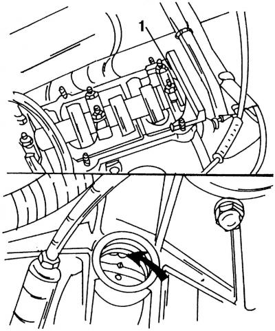
Fig. 415. The upper figure shows the adjusting gauge 1 installed on the camshaft. The lower figure shows how the flywheel with the TDC mark should be positioned
A special tool is required for further work (VW — 2065A, Ford — 21-105). The tool is an adjusting gauge for the camshaft, which is installed on the flywheel side after the engine is in the TDC position. Turn the engine so that the marking on the flywheel is in line with the adjusting journal (unscrew the plug from the top of the gearbox), as shown in Fig. 415. In order to make a precise adjustment, the following work should be performed:
- turn the camshaft so that the end of the adjusting gauge is located opposite the cylinder head;
- measure the gap on the other side with a feeler gauge;
- prepare a feeler gauge, the thickness of which is equal to half of the found value and slide it between the gauge and the cylinder head;
- now turn the camshaft so that the gauge overlaps the feeler gauges;
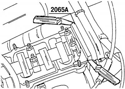
Fig. 416. Both feeler gauges are inserted between the adjusting gauge and the cylinder head surface
- insert a second feeler gauge of the same thickness from the other side between the gauge and the cylinder head. The operation is shown in Fig. 416.
Place the front of the vehicle on jack stands to allow access to the underside of the vehicle.
Disconnect the crankshaft vibration damper (4 bolts) and the water pump pulley (3 bolts). When performing this operation, these shafts must be fixed in a stationary position.
Remove the three bolts and remove the lower timing belt guard.
Lower the vehicle back to the ground.
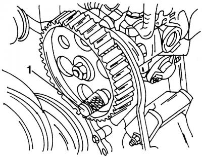
Fig. 417. Fixing the fuel injection pump gear in a stationary position with lock 1
To perform the following operation, you will again need a special tool - 2064 (VW) or 23 - 047 (Ford), which should be installed as shown in Fig. 417 on the fuel injection pump gear in order to fix it in a stationary position. The tool is a thrust pin with a diameter of 15.45 mm, which can be replaced by a round piece of some material. The thrust pin should be inserted through the hole in the fuel injection pump pulley into the corresponding hole in the pump bracket.
Remove the timing belt idler pulley located at the top of the timing belt.
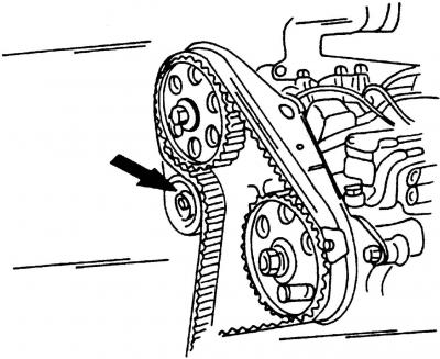
Fig. 418. After the tension roller shown by the arrow has been loosened, the belt can be removed
If you plan to reinstall the belt, make a mark on the belt to show the direction of its movement. After the nut is unscrewed, loosen the belt tensioner by turning it to the left. The device will release the belt (fig. 418, shown by arrow) and its tension will weaken.
Release the pulley and remove the drive belt from the gears.
The original article is available on the website: www.VWmanual.ru
Visitor comments