
Removing
ATTENTION: When carrying out all assembly work, in particular in the engine compartment due to the dense layout, pay attention to the following: lines of all kinds (e.g. fuel, hydraulic, activated carbon absorber, cooling system, refrigerant, brake lines, vacuum hoses), as well as electrical wires must be laid as they were originally laid. Ensure sufficient clearance to all moving and hot components to avoid damage of any kind to lines.
Remove the noise screen.
Remove the fan bracket along with the cooling fans.
Bring the radiator frame to the service position.
Mark the running direction of the V-ribbed belt and remove it.
Remove the right and left toothed belt covers.
Mark the direction of travel on the toothed belt with a waterproof felt-tip pen.
Bring the crankshaft to top dead center. The mark on the toothed belt cover A must align with the notch on the belt pulley B.
Check the position of the camshaft gears. Large holes in mounting plates (pic. 2.106) should be located opposite each other on the inside.
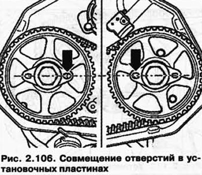
NOTE: If large holes are located on the outside of the gears, turn the crankshaft one more turn in the direction of engine rotation.
Unscrew the screw plug on the left of the cylinder block (rice. 2.100). The TDC hole of the crankshaft should be visible behind the hole in the screw plug and felt to the touch.
Carefully screw the fixing bolt 3242 into the hole until it stops and thus fix the crankshaft from turning.
Remove the middle toothed belt cover.
Unscrew the vibration damper.
NOTE: The vibration damper is attached to the crankshaft with 8 bolts.
First unscrew bolt 1 from the oil filter housing, then bolts 2 of the toothed belt tensioner cover (pic. 2.107).
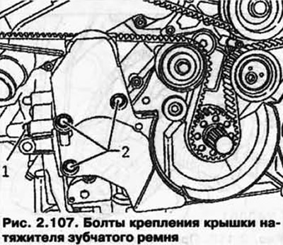
Remove the cover.
NOTE: The timing belt tensioner has an oil stop. Therefore, it shrinks slowly.
NOTE: Use lock pin T40011 to secure the tensioner.
NOTE: If necessary, align the holes in the housing and on the tensioner piston before tightening with needle nose pliers or thin wire.
Turn the toothed belt tensioner lever 1 with an Allen key in the direction (pic. 2.108).
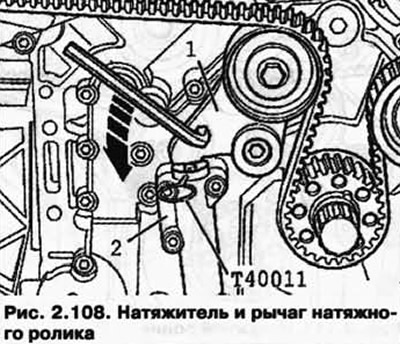
After the lever compresses the tensioner 2 so that the holes in the housing and the piston are opposite each other, fix the tensioner with the T40011 locking pin.
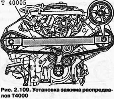
Insert the T4000 camshaft clamp into the camshaft mounting plates and loosen the fixing bolts by turning them about 5 turns (pic. 2.109).
Remove the T40005 camshaft clamp.
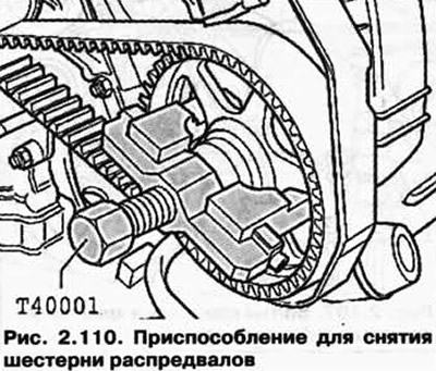
After that, using a two-handed puller T40001 and a hook T40001 / 2, remove the camshaft gears from the cone (pic. 2.110).
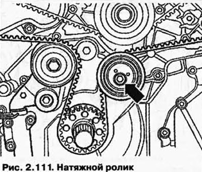
Unscrew the tension roller (see fig. 2.111) and remove the toothed belt.
Installation and tension
NOTE: If the belt has been used before, pay attention to the travel direction mark.
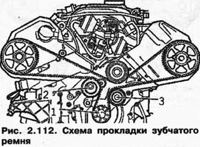
First lay the toothed belt on the crankshaft gear 1, then on the tensioner pulley 2 and then on the tension roller 3. Then, as shown in the figure, on the camshaft gears and the belt pulley of the cooling pump (pic. 2.112).
NOTE: The camshaft gears should rotate a little more on the camshaft cones.
Reinstall the T40005 camshaft clamp onto the gears.
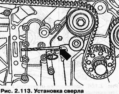
Place a 5mm drill bit between tensioner arm and tensioner piston (pic. 2.113).
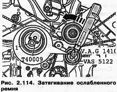
Tighten the still loosened tensioner roller with a VAG 1410 torque wrench with a VAS5122 ratchet and a tensioner wrench T40009 counterclockwise (pic. 2.114) with a tightening torque of 4 Nm.
In this position Tighten bolt 1 to 22 Nm.
After that, remove the 5mm drill bit.
Turn the toothed belt tensioner lever 1 with an Allen key in the direction (pic. 2.114).
After the lever compresses the piston in the toothed belt tensioner 2, remove the locking pin T40011.
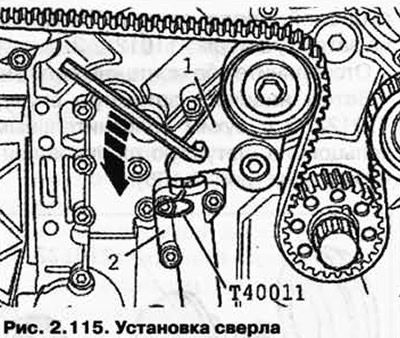
Turn the toothed belt tensioner lever 1 with an Allen key in the direction (pic. 2.115) and put a 7mm drill between the body and the lever.
Screw on the camshaft gears with a tightening torque of 55 Nm.
Remove the camshaft clamp - T40005.
Remove the drill bit inserted between the housing and the tension lever again.
Unscrew the fixing bolt 3242 from the hole, screw in the screw plug (rice. 2.101) and tighten it to 30 Nm.
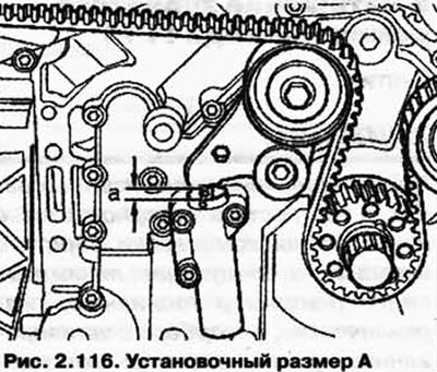
Rotate the crankshaft twice in the direction of rotation of the engine and check the installation dimension A (pic. 2.116). The specified value is 5 mm.
Further installation is carried out in the reverse order.
Visitor comments