
Removing
Bring the engine to TDC.
Remove toothed belt and camshaft gear, removal and installation of toothed belt, tension.
Left cylinder head
Remove the cylinder head cover.
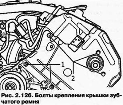
Unscrew fixing bolts 1 and 2 and remove the back cover of the toothed belt (pic. 2.126).
Right cylinder head
Remove the cylinder head cover.
Remove take-off roller 1.
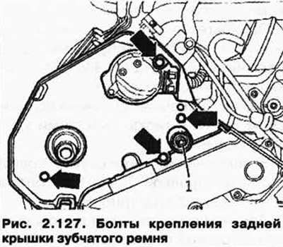
Loosen the fixing screws (see fig. 2.127) and remove the rear toothed belt cover.
Disconnect the plug from the Hall sensor and remove the housing together with the plug and cone.
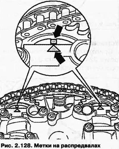
Check the TDC position of the camshafts. The markings on the camshafts must line up with both arrows on the bearing cap (pic. 2.128).
With further use of the old roller chain of the camshaft drive.
Before removing, mark the roller chain (pic. 2.129) (e.g. paint an arrow indicating the direction of the chain).
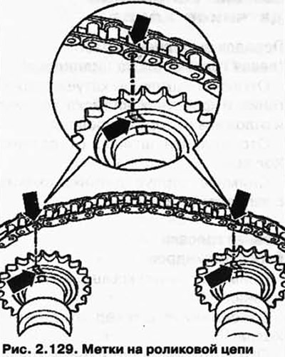
NOTE: Do not mark or score the chain with a center punch.
Fix the camshaft adjuster with the holder for chain tensioner 3366 (pic. 2.130).
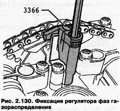
NOTE: If the chain tensioner is overtightened, the camshaft adjuster may be damaged.
Mark, as shown in the figure, regardless of the markings on the bearing caps, their mounting position and sequence (e.g. waterproof marker).
Remove the camshaft adjuster mounting bolts.
Remove bearing cover 1.
Remove bearing caps 2, 4, 6, 8 and 9 and follow the removal sequence (pic. 2.131).
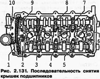
Unscrew bearing caps 3, 5 and 7 one by one crosswise and remove them.
Remove both camshafts with camshaft adjuster and lay them on a clean surface.
Installation
Replace the round plug.
Replace the camshaft adjuster gasket.
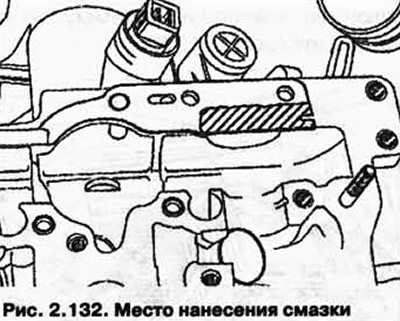
Lightly grease the sewn-in surface with AMV sealant 188 001 02 (pic. 2.132).
Lay the roller chain on the camshaft drive gears as follows.
With further use of the old roller chain of the camshaft drive.
Align Marks (pic. 2.129).
When using a new camshaft drive chain
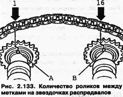
The distance between grooves A and B should be 16 chain rollers. The figure shows where the rollers 1 and 16 should be installed on the gears. The rollers of the chain 1 and 16 are shifted opposite the grooves A and B each by 1/2 tooth width to the left (pic. 2.133).
Insert the camshaft adjuster between the camshaft drive roller chain.
Insert the camshafts with roller chain and camshaft adjuster into the cylinder head.
Lubricate the grooves of the camshafts with engine oil.
NOTE: The fitted bushings for the bearing caps and the camshaft adjuster must be inserted into the cylinder head.
Install bearing caps 3, 5 and 7 according to the designation and screw with new bolts, alternating cross by cross. Tightening torque: 5 Nm + tighten 1/4 turn. (90°).
Screw on the camshaft adjuster 10. Tightening torque: 5 Nm + tighten 1/4 turn. (90°).
Install the chain tensioner.
Check the TDC position of the camshafts. The markings on the camshafts must line up with both arrows on the bearing cap (pic. 2.134).
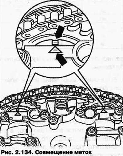
NOTE: Rotate the camshaft back and forth slightly if necessary to match the marks.
Lightly coat double bearing cap 6 and bearing cap 1 with AMV188 001 02 sealant and fit both caps. Tightening torque: 5 Nm + tighten 1/4 turn. (90°).
Install the remaining bearing caps. Tightening torque: 5 Nm + tighten 1/4 turn. (90°).
Replace camshaft seals.
Replace Hall sensor seals.
Gently push the cover in with the stop of clamping sleeve 3202.
Further installation is carried out in the reverse order.
NOTE: After installing the camshafts, the engine must not be started for approximately 30 minutes. Hydraulic compensators must be upset. (Otherwise, the valves will touch the pistons). After working on the valve train, rotate the engine by hand to make sure that no valve is in contact with the piston.
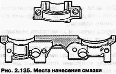
Before installing, apply a small amount of sealant AMV 188 001 02 to the joints of the front and rear bearing caps (pic. 2.135).
Visitor comments