
Mechanical transmission 08D car Volkswagen Touareg 1

Transfer case marking
NOTE: As an alternative to automatic transmission «09D» with some engine variants, a manual transmission is also installed «08D». The OAD transfer case is designed for 09D...
NOTE: As an alternative to automatic transmission «09D» with some engine variants, a manual transmission is also installed «08D». The OAD transfer case is designed for 09D...
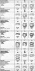
Letter designations, filling volumes of units (transfer case)
Table 3.8 Letter designations, compatibility, filling volumes of units (transfer case)
Table 3.8 Letter designations, compatibility, filling volumes of units (transfer case)
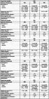
Letter designations, gear ratios, filling volumes (main forward gear)
Table 3.9 Letter designations, compatibility of units, gear ratios, filling volumes (main forward gear)
Table 3.9 Letter designations, compatibility of units, gear ratios, filling volumes (main forward gear)
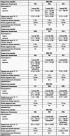
Letter designations, gear ratios, filling capacities (main reverse gear)
Table 3.10 Letter designations, compatibility of units, gear ratios, filling capacities (main reverse gear) Rear final drive «FWG»: in conjunction with automatic transmission 09D...
Table 3.10 Letter designations, compatibility of units, gear ratios, filling capacities (main reverse gear) Rear final drive «FWG»: in conjunction with automatic transmission 09D...

Front final drive marking
NOTE: OAA front final drive is designed for 09D automatic transmission and 08D manual transmission. The location of the marking on the front final drive The location on the front...
NOTE: OAA front final drive is designed for 09D automatic transmission and 08D manual transmission. The location of the marking on the front final drive The location on the front...

Rear final drive marking
NOTE: The OAB/OAC rear final drive is designed for 09D automatic transmission and 08D manual transmission. The location of the marking on the rear final drive of the letter...
NOTE: The OAB/OAC rear final drive is designed for 09D automatic transmission and 08D manual transmission. The location of the marking on the rear final drive of the letter...

General information about the gearbox
Transmission When installing the transfer case, make sure that the fitted bushing is in the correct position between the transfer case and the gearbox. When installing bearing...
Transmission When installing the transfer case, make sure that the fitted bushing is in the correct position between the transfer case and the gearbox. When installing bearing...

Electronic components and their installation locations on the transfer case
Pic. 3.88. Electrical/electronic components and their installation locations on the transfer case: 1 - transfer box control unit; 2 - transfer case control; 3 - electric motor of...
Pic. 3.88. Electrical/electronic components and their installation locations on the transfer case: 1 - transfer box control unit; 2 - transfer case control; 3 - electric motor of...

Removal and installation of the transfer case control E473
Diagnostic connector The diagnostic connector is located at the bottom of the front panel, under the casing, in the driver's footwell (pic. 3.91). Installation location of idle...
Diagnostic connector The diagnostic connector is located at the bottom of the front panel, under the casing, in the driver's footwell (pic. 3.91). Installation location of idle...

Removing and installing transfer case control unit J646
Removing Remove the front right seat. If so, remove the seat frame trim. First you need to check if the radio with encoding is installed in the car. If yes, then you should find...
Removing Remove the front right seat. If so, remove the seat frame trim. First you need to check if the radio with encoding is installed in the car. If yes, then you should find...

Removing the transfer case
Raise the vehicle. Remove a noise isolation under a transmission. If available, dismantle the bottom protection under the transfer case. Remove the rear of the exhaust system and,...
Raise the vehicle. Remove a noise isolation under a transmission. If available, dismantle the bottom protection under the transfer case. Remove the rear of the exhaust system and,...

Transfer box installation
Installation is carried out in the reverse order, paying attention to the following. If necessary, use matched bushings to center the transfer case and gearbox. Always replace the...
Installation is carried out in the reverse order, paying attention to the following. If necessary, use matched bushings to center the transfer case and gearbox. Always replace the...

Laying the ventilation tube on the transfer case
Transfer case vent tube 1 runs through transfer case and manual transmission to coolant hose 4 (pic. 3.101). At the same time, it will fit into holders 2 on the transfer case and...
Transfer case vent tube 1 runs through transfer case and manual transmission to coolant hose 4 (pic. 3.101). At the same time, it will fit into holders 2 on the transfer case and...

Replacing the rubber-metal support of the gearbox bracket
Remove the gearbox bracket. Press out the rubber-metal support (pic. 3.102). Screw the new rubber-metal support to the T10214/3 stop. Press rubber-metal bearing A with stop...
Remove the gearbox bracket. Press out the rubber-metal support (pic. 3.102). Screw the new rubber-metal support to the T10214/3 stop. Press rubber-metal bearing A with stop...

Checking the oil level in the transfer case
Remove the oil level screw (pic. 3.106). The oil level is sufficient if it is within the lower edge of the filler hole. Screw in and tighten the new bolt. When filling oil, pay...
Remove the oil level screw (pic. 3.106). The oil level is sufficient if it is within the lower edge of the filler hole. Screw in and tighten the new bolt. When filling oil, pay...

Removal and installation of sealing rings of the flange of the power take-off shaft / cardan shaft and the transfer case motor
Pic. 3.107. Transfer case components: 1 - nut, 130 Nm; 2 - O-ring; 3 - flange of the power take-off shaft; 4 - metal anther; 5 - sealing ring; 6 - ventilation tube; 7 - sealing...
Pic. 3.107. Transfer case components: 1 - nut, 130 Nm; 2 - O-ring; 3 - flange of the power take-off shaft; 4 - metal anther; 5 - sealing ring; 6 - ventilation tube; 7 - sealing...

Replacing the sealing ring of the flange of the PTO shaft / front propeller shaft (transfer box installed)
Removing Remove the front propeller shaft. Fasten counterholder 3145 with 2 bolts M 10x25 on the PTO flange (pic. 3.118). Loosen the PTO flange nuts. Remove the PTO flange. Remove...
Removing Remove the front propeller shaft. Fasten counterholder 3145 with 2 bolts M 10x25 on the PTO flange (pic. 3.118). Loosen the PTO flange nuts. Remove the PTO flange. Remove...

Replacing the sealing ring of the flange of the PTO shaft / rear propeller shaft (transfer box installed)
Removing Remove the rear driveshaft. Loosen the PTO flange nuts (pic. 3.121). A - Hexagon bolt M 10x30 with nuts. Remove the PTO flange. Remove the O-ring using the VW 771...
Removing Remove the rear driveshaft. Loosen the PTO flange nuts (pic. 3.121). A - Hexagon bolt M 10x30 with nuts. Remove the PTO flange. Remove the O-ring using the VW 771...

Removing the transfer case motor V253
If the V253 transfer case motor is replaced, keep the following in mind. The new transfer case motor is adjusted to the prescribed position. To facilitate installation, adjust...
If the V253 transfer case motor is replaced, keep the following in mind. The new transfer case motor is adjusted to the prescribed position. To facilitate installation, adjust...

Installing the transfer case motor V253
If a new transfer case motor is installed, observe the following. The control element of the transfer case E473, with the ignition off, is turned to the position «LOW». Transfer...
If a new transfer case motor is installed, observe the following. The control element of the transfer case E473, with the ignition off, is turned to the position «LOW». Transfer...

Checking the oil level in the final drive of the front axle
Remove the oil level screw (pic. 3.127). The oil level is sufficient if it is within the lower edge of the front final drive filler hole. Tighten the bolt with a new sealing ring....
Remove the oil level screw (pic. 3.127). The oil level is sufficient if it is within the lower edge of the front final drive filler hole. Tighten the bolt with a new sealing ring....
This section is available on russian, bulgarian, belarusian, ukrainian, serbian, croatian, romanian, polish, slovak, hungarian
Similar sections from other manuals for VW cars:
General information: User manual Volkswagen Passat B2 (1981-1988)
General information: User manual Volkswagen Golf 1 (1974-1984, petrol)
General information: User manual Volkswagen Polo 4 (2001-2009)
Transmission: 6-speed manual gearbox 0A6 Volkswagen Tiguan 1 (2007-2015)
General information: User manual Volkswagen Transporter T4 (1990-2003)
General information: User manual Volkswagen Caddy 3 (2003-2010)
Touareg 1
- General information
- Vehicle device
- Controls and instruments
- Seats and safety
- Maintenance and management
- Power unit
- Engine checks
- Petrol engine 3.2L
- Petrol engine 4.2L
- Diesel engine 5.0L
- Cooling system
- Lubrication system
- Injection system
- Exhaust system
- Fuel supply system
- Transmission
- Automatic gearbox 09D
- Mechanical gearbox 08D
- Cardan shaft
- Chassis
- Wheels and tires
- Front suspension
- Rear suspension
- Steering gear
- Brake system
- Body
- Outdoor elements
- Electrical equipment
- Battery
- Generator and starter
- Instruments and wipers
VWmanual.ru © 2016-2024 | Mobile version | News and articles | Sitemap: EN BG BY UA RS HR RO PL SK HU | Write message | Site search
Passat B2 • Passat B3 • Passat B4 • Passat B5 • Passat B6 • Golf 1, diesel • Golf 1, petrol • Golf 2, petrol • Golf 2 • Golf 3 • Golf 4 • Golf 5 • Polo 3 • Polo 4 • Touareg 1 • Tiguan 1 • Sharan 1 • Transporter T3 • Transporter T4 • Beetle • Caddy 3 •
Passat B2 • Passat B3 • Passat B4 • Passat B5 • Passat B6 • Golf 1, diesel • Golf 1, petrol • Golf 2, petrol • Golf 2 • Golf 3 • Golf 4 • Golf 5 • Polo 3 • Polo 4 • Touareg 1 • Tiguan 1 • Sharan 1 • Transporter T3 • Transporter T4 • Beetle • Caddy 3 •