
Brake system of car Volkswagen Touareg 1

Example of a vehicle data plate
Arrow 1 - rear wheel brake - 1KF. Arrow 2 - front wheel brake - 1LC. The vehicle data sticker is located in the spare wheel well and in the service book. The tables below show the...
Arrow 1 - rear wheel brake - 1KF. Arrow 2 - front wheel brake - 1LC. The vehicle data sticker is located in the spare wheel well and in the service book. The tables below show the...
Front brakes
Pos. PR number (Pr.-Nr.) 1LB 1 Stopping support FN 3 (16'') 2 Brake lining, thickness, mm 12,5 3 Brake disc, mm 308 Brake disc, thickness, mm 29,5 4 Brake caliper, piston, mm 60...
Pos. PR number (Pr.-Nr.) 1LB 1 Stopping support FN 3 (16'') 2 Brake lining, thickness, mm 12,5 3 Brake disc, mm 308 Brake disc, thickness, mm 29,5 4 Brake caliper, piston, mm 60...
Rear brakes
Pos. PR number (Pr.-Nr.) 1KE 1 Stopping support FN 44 (16'') 2 Brake lining, thickness, mm 13 3 Brake disc, mm 314 Brake disc, thickness, mm 22 4 Brake caliper, piston, mm 44 Pos....
Pos. PR number (Pr.-Nr.) 1KE 1 Stopping support FN 44 (16'') 2 Brake lining, thickness, mm 13 3 Brake disc, mm 314 Brake disc, thickness, mm 22 4 Brake caliper, piston, mm 44 Pos....

Checking the brake system
Examination The brake system is tested on an adjustable counter-roller brake test rig. The counter-rotating rollers on the brake tester rotate forward on one side and backward on...
Examination The brake system is tested on an adjustable counter-roller brake test rig. The counter-rotating rollers on the brake tester rotate forward on one side and backward on...
Bleeding the brake system
NOTES: Bleeding the brake systems of vehicles equipped with ABS is carried out in the same way as for vehicles without this system. New DOT 4 brake fluid is used. Genuine VW/Audi...
NOTES: Bleeding the brake systems of vehicles equipped with ABS is carried out in the same way as for vehicles without this system. New DOT 4 brake fluid is used. Genuine VW/Audi...
Pumping (main)
Strictly follow the procedure for bleeding the brake system. Brembo brake calipers have two bleeders. Always bleed at two bleed ports. Bleed at the external bleeder first. Connect...
Strictly follow the procedure for bleeding the brake system. Brembo brake calipers have two bleeders. Always bleed at two bleed ports. Bleed at the external bleeder first. Connect...
Additional pumping
An assistant is needed to complete this work. Firmly press and do not release the brake pedal. Open the brake caliper bleeder. Press the brake pedal all the way. Close the fitting...
An assistant is needed to complete this work. Firmly press and do not release the brake pedal. Open the brake caliper bleeder. Press the brake pedal all the way. Close the fitting...

Removal and installation of brake booster membrane travel potentiometer G420
Pic. 6.9. Brake Booster/Brake Master Cylinder: 1 - support bracket of the pedal assembly; 2 - hex nut, self-locking, 25 Nm; 3 - brake pedal; 4 - seal; 5 - tandem type brake...
Pic. 6.9. Brake Booster/Brake Master Cylinder: 1 - support bracket of the pedal assembly; 2 - hex nut, self-locking, 25 Nm; 3 - brake pedal; 4 - seal; 5 - tandem type brake...

Removing and installing brake vacuum pump V192
Pic. 6.11. Vacuum brake pump V192: 1 - boost pressure sensor in the brake system; 2 - vacuum hose; 3 - brake booster relay; 4 - check valve; 5 - collar; 6 - clip; 7 - emphasis; 8...
Pic. 6.11. Vacuum brake pump V192: 1 - boost pressure sensor in the brake system; 2 - vacuum hose; 3 - brake booster relay; 4 - check valve; 5 - collar; 6 - clip; 7 - emphasis; 8...

Removing and installing brake booster pressure sender G294
Removing Remove the plenum box cover. Disconnect connector 1 (pic. 6.14). Carefully pry down the brake booster pressure sender G294 and remove it (pic. 6.15). Installation...
Removing Remove the plenum box cover. Disconnect connector 1 (pic. 6.14). Carefully pry down the brake booster pressure sender G294 and remove it (pic. 6.15). Installation...
Removal and installation of the main brake cylinder
Removing Remove the plenum box cover. Remove the engine compartment seal and the bar in the area of the brake booster. Remove the wall from the drainage box. Place a sufficient...
Removing Remove the plenum box cover. Remove the engine compartment seal and the bar in the area of the brake booster. Remove the wall from the drainage box. Place a sufficient...

Removal and installation of the brake booster
Removing Remove the upholstery on the driver's side. Remove the brake light switch/brake pedal switch. Remove the brake light switch holder. Disconnect the brake pedal from the...
Removing Remove the upholstery on the driver's side. Remove the brake light switch/brake pedal switch. Remove the brake light switch holder. Disconnect the brake pedal from the...

Repair of brake pipelines
With the pipe flaring tool VAS 6056, brake pipes with an outside diameter of 5 mm can be flared without damaging the coatings. Due to this, in certain cases, it is possible to...
With the pipe flaring tool VAS 6056, brake pipes with an outside diameter of 5 mm can be flared without damaging the coatings. Due to this, in certain cases, it is possible to...

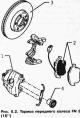
Front wheel brake repair, Brembo 17 brake caliper (1LC)
NOTE: To drain the brake fluid from the reservoir, use the MS 5234 brake system filling and bleeder or the VAG 1869/4 brake system filling and bleeder. Before dismantling the...
NOTE: To drain the brake fluid from the reservoir, use the MS 5234 brake system filling and bleeder or the VAG 1869/4 brake system filling and bleeder. Before dismantling the...

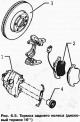
Rear wheel brake repair, brake caliper FN 44
Pic. 6.41. Rear brake components: 1 - brake disc / brake drum; 2 - set bolt, 20 Nm; 3 - bracket-holder; 4 - hex bolt, 200 Nm; 5 - brake pads; 6 - holding spring; 7 - brake...
Pic. 6.41. Rear brake components: 1 - brake disc / brake drum; 2 - set bolt, 20 Nm; 3 - bracket-holder; 4 - hex bolt, 200 Nm; 5 - brake pads; 6 - holding spring; 7 - brake...

Parking brake adjustment
Adjustments can only be made using the adjustment devices on the two rear wheels. Adjustment cannot be made on the parking brake lever and the transmission module on the center...
Adjustments can only be made using the adjustment devices on the two rear wheels. Adjustment cannot be made on the parking brake lever and the transmission module on the center...

Adjustment of brake pads on two wheels
Insert a screwdriver into the hole in the brake disc and turn the adjusting nut A against the resistance of the return spring B until the brake disc stops rotating (pic. 6.48)....
Insert a screwdriver into the hole in the brake disc and turn the adjusting nut A against the resistance of the return spring B until the brake disc stops rotating (pic. 6.48)....

Checking the free travel of the pedal parking brake lever
Pic. 8.49. Pedal parking brake lever: 1 - brake release lever; 2 - pull release from the brake; 3 - emphasis; 4 - foot parking brake; 5 - hex bolt, 23 Nm; 6 - hex bolt, 23 Nm; 7 -...
Pic. 8.49. Pedal parking brake lever: 1 - brake release lever; 2 - pull release from the brake; 3 - emphasis; 4 - foot parking brake; 5 - hex bolt, 23 Nm; 6 - hex bolt, 23 Nm; 7 -...

Removal and installation of the lever of a pedal parking brake
Removing Remove the upholstery on the driver's side. Disconnect the plug from the parking brake contact switch. Remove the left fuse box and set it aside with the wiring harness...
Removing Remove the upholstery on the driver's side. Disconnect the plug from the parking brake contact switch. Remove the left fuse box and set it aside with the wiring harness...

Removal and installation of rear brake cables
Removing Remove the two rear wheels. Remove the center console. Before unscrewing the hexagon nut 1, measure the value a (pic. 6.55). Record the resulting value. Slightly turn hex...
Removing Remove the two rear wheels. Remove the center console. Before unscrewing the hexagon nut 1, measure the value a (pic. 6.55). Record the resulting value. Slightly turn hex...

Disconnecting the brake pedal from the brake booster
Pic. 6.57. Brake pedal (for automatic transmission): 1 - support bracket of the pedal assembly; 2 - hex nut, self-locking, 20 Nm; 3 - finger; 4 - brake pedal; 5 - bearing shell; 6...
Pic. 6.57. Brake pedal (for automatic transmission): 1 - support bracket of the pedal assembly; 2 - hex nut, self-locking, 20 Nm; 3 - finger; 4 - brake pedal; 5 - bearing shell; 6...
Connecting the brake pedal to the brake booster
Hold the ball head of the push rod before fastening and depress the brake pedal towards the brake booster until the ball head clicks into place with an audible click. Further...
Hold the ball head of the push rod before fastening and depress the brake pedal towards the brake booster until the ball head clicks into place with an audible click. Further...

Removal, installation and adjustment of the switch of signals of braking
Removing Remove the upholstery on the driver's side. Remove the plug from the brake light switch (pic. 6.59). Remove the brake light switch by turning 45°to the left. Removal and...
Removing Remove the upholstery on the driver's side. Remove the plug from the brake light switch (pic. 6.59). Remove the brake light switch by turning 45°to the left. Removal and...

Anti-lock braking system (ABS)
The brake system with ABS is dual-circuit and diagonal. Strengthening in the brake system is carried out using a vacuum booster. ABS malfunctions affect the brake system and the...
The brake system with ABS is dual-circuit and diagonal. Strengthening in the brake system is carried out using a vacuum booster. ABS malfunctions affect the brake system and the...

Electrical and electronic components of the brake system
The electrical/electronic components of the ABS system are shown in fig. 6.62. Pic. 6.62. Electrical/Electronic Components: 1 - ABS hydraulic block; 2 - ABS control unit; 3 -...
The electrical/electronic components of the ABS system are shown in fig. 6.62. Pic. 6.62. Electrical/Electronic Components: 1 - ABS hydraulic block; 2 - ABS control unit; 3 -...
This section is available on russian, bulgarian, belarusian, ukrainian, serbian, croatian, romanian, polish, slovak, hungarian
Similar sections from other manuals for VW cars:
Chassis: Brake system Volkswagen Passat B2 (1981-1988)
Chassis: Brake system Volkswagen Golf 3 (1991-1997)
Chassis: Brake system Volkswagen Polo 3 (1995-2003)
Chassis: Brake system Volkswagen Tiguan 1 (2007-2015)
Chassis: Brake system Volkswagen Sharan 1 (1995-2000)
Chassis: Brake system Volkswagen Transporter T3 (1979-1992)
Chassis: Brake system Volkswagen Caddy 3 (2003-2010)
Touareg 1
- General information
- Vehicle device
- Controls and instruments
- Seats and safety
- Maintenance and management
- Power unit
- Engine checks
- Petrol engine 3.2L
- Petrol engine 4.2L
- Diesel engine 5.0L
- Cooling system
- Lubrication system
- Injection system
- Exhaust system
- Fuel supply system
- Transmission
- Automatic gearbox 09D
- Mechanical gearbox 08D
- Cardan shaft
- Chassis
- Wheels and tires
- Front suspension
- Rear suspension
- Steering gear
- Brake system
- Body
- Outdoor elements
- Electrical equipment
- Battery
- Generator and starter
- Instruments and wipers
VWmanual.ru © 2016-2024 | Mobile version | News and articles | Sitemap: EN BG BY UA RS HR RO PL SK HU | Write message | Site search
Passat B2 • Passat B3 • Passat B4 • Passat B5 • Passat B6 • Golf 1, diesel • Golf 1, petrol • Golf 2, petrol • Golf 2 • Golf 3 • Golf 4 • Golf 5 • Polo 3 • Polo 4 • Touareg 1 • Tiguan 1 • Sharan 1 • Transporter T3 • Transporter T4 • Beetle • Caddy 3 •
Passat B2 • Passat B3 • Passat B4 • Passat B5 • Passat B6 • Golf 1, diesel • Golf 1, petrol • Golf 2, petrol • Golf 2 • Golf 3 • Golf 4 • Golf 5 • Polo 3 • Polo 4 • Touareg 1 • Tiguan 1 • Sharan 1 • Transporter T3 • Transporter T4 • Beetle • Caddy 3 •