
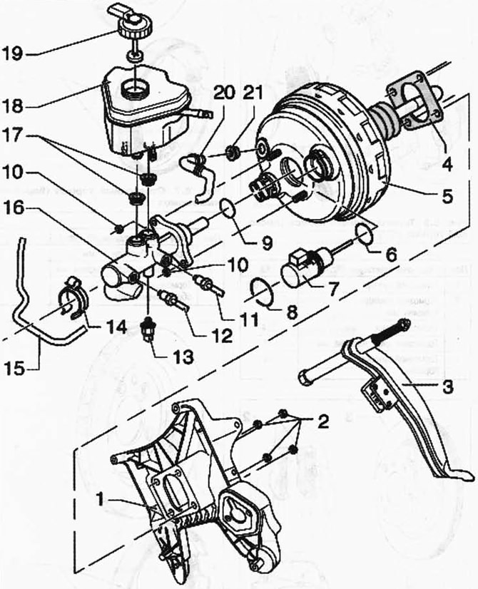
Pic. 6.9. Brake Booster/Brake Master Cylinder:
1 - support bracket of the pedal assembly; 2 - hex nut, self-locking, 25 Nm; 3 - brake pedal; 4 - seal; 5 - tandem type brake booster; 6 - sealing ring; 7 - brake booster diaphragm travel potentiometer; 8 - spring retaining ring; 9 - sealing ring; 10 - hex nut, self-locking, 25 Nm; 11 - brake pipeline, 14 Nm; 12 - brake pipeline, 14 Nm; 13 - pressure sensor of the brake system; 14 - bracket; 15 - brake pipeline; 16 - main brake cylinder; 17 - sealing plug; 18 - reservoir with brake fluid; 19 - cover; 20 - vacuum hose; 21 - sealing plug.
NOTE: Use only new brake fluid. Follow the instructions on the brake fluid packaging.
Removing
Remove the plenum box cover.
Disconnect the plug from the spring travel potentiometer.
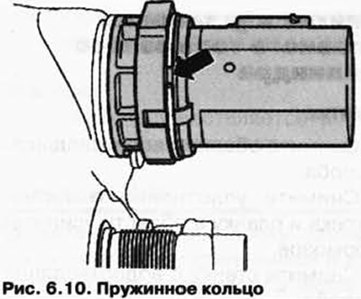
Remove the circlip from the groove and the diaphragm travel potentiometer from the brake booster (pic. 6.10).
Installation
Installation is carried out in the reverse order.
Visitor comments