



Removal
Disconnect the battery.
Remove the air intake sleeve, air filter housing (in vehicles with diesel engines and some petrol engines) and battery.
In vehicles with a 6-cyl. petrol engine, the battery is located in the luggage compartment; accordingly, it is necessary to remove the air filter housing with the bracket. Additionally, it is necessary to remove and put aside the external starting module with the holder.
Remove the battery holder frame.
Place a sufficient amount of lint-free cloth in the engine and gearbox areas.
Remove as much brake fluid as possible using a filler and bleeder or a brake fluid reservoir device.
For vehicles with manual transmission
Clamp the clutch master cylinder hose B using a clamp to 25 mm.
Remove the clutch master cylinder hose B.
Continuation of installation operations for all vehicles
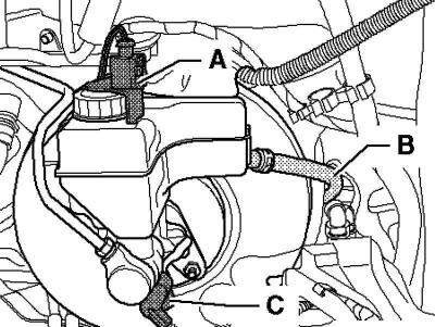
Fig. 6.46. Clutch release master cylinder plug connection and hose
Remove plug connection A from the float warning indicator sensor (Fig. 6.46).
Remove plug connection C from brake light switch F.
Note: For vehicles with HBV (hydraulic brakes with vacuum booster) disconnect the plug connection from the brake booster low pressure sensor.
Remove the vacuum hose from the brake booster.
For vehicles with manual transmission
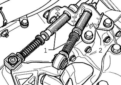
Fig. 6.48. Cable drives and counter support
Unscrew the cable drives 1, unscrew the counter support 2 and put it aside (Fig. 6.48).
For vehicles with a 2-liter TDI engine
Remove the boost tube and pull it as far in front of the transmission as possible.
For cars with automatic transmission
Open the cable channel and remove the Servotronic system wiring harness, remove the cable channel from the console and set it aside.
Pry the gear selector lever cable out of the counter support and holder, set aside
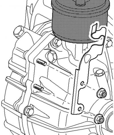
Fig. 6.49. Gear selector lever cable holder
Remove the gear selector lever cable holder (Fig. 6.49).
For vehicles with a 2-litre 110 kW FSI engine
Remove the EGR connecting pipe and the coolant hose holder from the cylinder head.
Continuation of installation operations for all vehicles
Unscrew the brake pipes on the brake master cylinder, close the brake pipes using the plugs from the repair kit 1H0 698 311 A.
In vehicles with 6-cyl. petrol engine
Loosen the master cylinder nuts.
Carefully remove the brake master cylinder from the brake booster and remove the heat shield.
Remove the brake booster vacuum sensor.
Continuation of description of works for all cars
Loosen the mounting nuts and remove the driver's footwell trim.
Disconnect the brake pedal from the brake booster.
Unscrew nuts 1 of the brake booster.
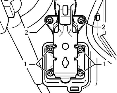
Fig. 6.50. Brake booster and support bracket mounting nuts
Loosen the two upper nuts 2 of the support bracket (Fig. 6.50).
Remove the brake booster from the vehicle.
Loosen the master cylinder nuts.
Carefully remove the brake master cylinder from the brake booster.
Installation
Installation is carried out in reverse order.
Please consider the following factors when installing.
Connect the brake pedal to the brake booster.
After installation, bleed the brake system and clutch.
Tightening torques
Brake booster to pedal assembly/bulkhead: 25 Nm.
Master cylinder to brake booster: 25 Nm.
Brake pipes to the main brake cylinder: 8.5 mm – 17 Nm, 6 mm – 14 Nm.
The original information is posted on the website [www.VWManual.ru]
Visitor comments