
English Русский
Български
Беларускі
Український
Српски
Hrvatski
Română
Polski
Slovenský
Magyar
  |  Articles  |  Sitemap  |  Contacts  |    |
Car maintenance Ford Car maintenance Hyundai Car maintenance Chevrolet Car maintenance BMW Car maintenance Audi Car maintenance Opel Car maintenance AvtoVAZ
VWmanual.ru


Main   Passat   Golf   Polo   Touareg   Tiguan   Sharan   Transporter   Others  
Passat B2 (1981-1988) Passat B3 (1988-1993) Passat B4 (1988-1996) Passat B5 (1996-2005) Passat B6 (2005-2010)

Repair of brake pipes (VW Passat B6)

  • Main
  • Passat
  • Passat B6
  • Chassis
  • Brake system
  • Repair of brake pipes
            0


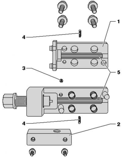
The VAS 6056 tube flaring device can be used to flare brake pipes with an external diameter of 5 mm without damaging the coating. This means that individual parts of the brake pipes can be replaced in certain cases, which reduces repair costs.

Fig. 6.51. Device for flaring pipes: 1 – upper part of the pipe flaring device; 2 – handle mount; 3…

Fig. 6.51. Device for flaring pipes: 1 – upper part of the pipe flaring device; 2 – handle mount; 3 – locking screw; 4 – headless screws for clamps; 5 – clamps


Working with the VAG 1356 pipe flaring tool on black brake lines is not permitted due to their coating and diameter.
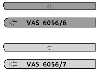
Fig. 6.52. Marking of clamps

Fig. 6.52. Marking of clamps


Note: The arrow on the round side of the clamps must point towards the edge of the housing and the straight side of the clamps must be installed towards the spindle, otherwise the flaring head will not form correctly (fig. 6.52Note:).


Work manual


Unscrew the necessary brake pipe from the caliper or brake cylinder, place a container under the leaking brake fluid and dispose of it properly.
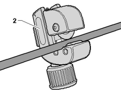
Fig. 6.53. Cutting the brake pipe

Fig. 6.53. Cutting the brake pipe


Cut the brake pipe at a suitable place (straight section with free access) using pipe cutter 2 (Fig. 6.53).

Remove the defective section.

Degrease the surface of the brake pipe.
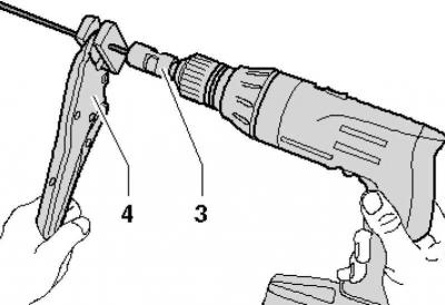
Fig. 6.54. Installing the turning tool on the brake pipe

Fig. 6.54. Installing the turning tool on the brake pipe


Clamp the brake pipe in pliers 4 so that about 50 mm protrudes from the plastic clamping jaws (Fig. 6.54).

Clamp the turning tool 3 in the drill and place it on the brake pipe.

Using a low speed drill and light pressure, grind away the coating from the brake pipe.

The turning length is set by the stop in the turning tool.


Remove the grinding tool from the brake pipe and remove any remaining chips.
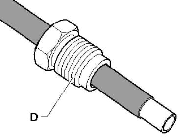
Fig. 6.55. Installing the nozzle

Fig. 6.55. Installing the nozzle


Remove the pliers and place the D fitting on the brake pipe (Fig. 6.55).
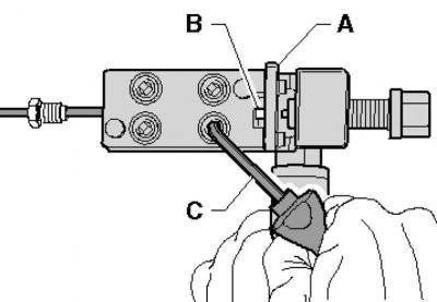
Fig. 6.56. Installing the tube into the flaring device

Fig. 6.56. Installing the tube into the flaring device


Insert tube B into the flaring tool until it stops A (Fig. 6.56).

Note: The tube must be against the stop when tightening the hex screws, otherwise the flaring head will not fit correctly.


Pre-clamp the tube in the flaring tool so that it does not move any more. Then fold the stop A upwards and tighten the hexagon screws crosswise with the angle screwdriver C.
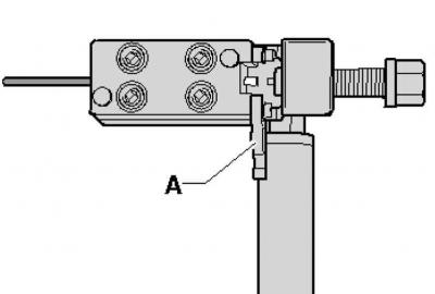
Fig. 6.57. Screwing in the spindle

Fig. 6.57. Screwing in the spindle


Screw the spindle into the flaring device until it stops (Fig. 6.57).

Unscrew the spindle again.

Loosen the hex screws in a cross pattern.

The original can be viewed on the portal vwmanual.ru

Remove the tube from the flaring tool, clean it and inspect the brake tube and flaring.

Clean the remaining part of the brake pipe on the vehicle:

Connect the brake filling and bleeding device, place the bleeder bottle hose onto the flare and operate the brake filling and bleeding device briefly to allow a small amount of brake fluid to flow out.

Blow out the treated brake pipe with compressed air.
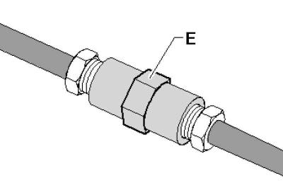
Fig. 6.58. Connecting tubes with an adapter

Fig. 6.58. Connecting tubes with an adapter


Connect the brake pipes with adapter E (Fig. 6.58).

Install the brake line.

Bleed the brake system.

This article is available at russian, bulgarian, belarusian, ukrainian, serbian, croatian, romanian, polish, slovak, hungarian
The text has been checked: Orlov Dmitry

Share information:

Previous articles
Removal and installation the brake booster
Removal and installation the master brake cylinder
Removal and installation the brake light switch F
Removal and installation the brake caliper piston
Removal and installation the piston for the FN 3 brake caliper
Connecting the brake pedal to the brake booster
Next articles
General information about the anti-lock braking system
Removal and installation the speed sensor on the front axle
Removal and installation the speed sensor on the rear axle
Removal and installation the speed sensor on the rear axle (all-wheel drive)
Removal and installation the low pressure sensor in the brake booster
Possible malfunctions, their causes and methods of elimination


Similar articles from other manuals for VW cars:
Front brake disc repair Golf 2 (1984-1993)
Parking brake system actuator lever Polo 3 (1995-2003)
Repair of brake pipes Touareg 1 (2002-2006)
Connecting brake pipes from the master cylinder to the hydraulic… Tiguan 1 (2007-2015)
Repair of the main brake cylinder Sharan 1 (1995-2000)
Checking brake pipes by visual inspection Transporter T4 (1990-2003)
Brake caliper repair (FS III) Caddy 3 (2003-2010)
Link to this page in different formats


Visitor comments


No comments yet


How much will 29 + 13 =


Passat B6 
  • General information
  • User manual
  • Maintenance
  • Petrol engine 1.6L
  • Engine repair
  • Cooling and lubrication system
  • Fuel injection system
  • Petrol engine 2.0L
  • Engine repair
  • Lubrication system
  • Cooling system
  • Fuel and exhaust systems
  • Diesel engine 2.0L
  • Engine repair
  • Cooling and lubrication system
  • Fuel and exhaust systems
  • Transmission
  • Clutch
  • Mechanical gearbox
  • Automatic gearbox
  • Drive shafts
  • Chassis
  • Wheels and tires
  • Car suspension
  • Steering
  • Brake system
  • Body
  • Exterior (external elements)
  • Electrical equipment
  • Power devices
  • Lighting and appliances
  • Electrical circuits
Passat B5 
  • General information
  • User manual
  • Weekly checks
  • Maintenance
  • Power unit
  • Engine repair
  • Cooling system
  • Fuel system (petrol)
  • Fuel system (diesel)
  • Engine management
  • Exhaust system
  • Transmission
  • Clutch
  • Car gearbox
  • Drive shafts
  • Chassis
  • Car suspension
  • Wheels and tires
  • Steering
  • Brake system
  • Body
  • Exterior (external elements)
  • Interior (internal elements)
  • Doors and covers
  • Ventilation and heating
  • Electrical equipment
  • Power devices
  • Lighting and appliances
  • Electrical circuits
Passat B4 
  • General information
  • User manual
  • Maintenance
  • Technical data
  • 8-valve engine
  • Engine repair
  • Cooling and lubrication system
  • Supply system
  • Ignition system
  • Fuel injection «Mono-Jetronic»
  • Control system «Mono-Motronic»
  • Control system «Digifant»
  • Control system «Simos»
  • 16-valve engine
  • Engine repair
  • Cooling and lubrication system
  • Fuel injection «K-Jetronic»
  • Control system «KE-Motronic»
  • Control system «Digifant»
  • Diesel engine
  • Engine repair
  • Cooling and lubrication system
  • Power and control system
  • Turbocharging system
  • Digital control system
  • Transmission
  • Clutch
  • Manual gearbox
  • Hydromechanical gearbox
  • Front wheel drive
  • Chassis
  • Car suspension
  • Steering
  • Brake system
  • Body
  • Body elements
  • Electrical equipment
  • Power devices
  • Lighting and appliances
  • Electrical circuits
Passat B3 
  • General information
  • User manual
  • Driving Tips
  • Maintenance instructions
  • Technical data
  • Power unit
  • Engine repair
  • Ignition system
  • Lubrication system
  • Cooling system
  • Supply system
  • Petrol injection system
  • Diesel engine
  • Exhaust system
  • Transmission
  • Clutch
  • Car gearbox
  • Chassis
  • Suspension
  • Steering
  • Brake system
  • Wheels and tires
  • Body
  • Exterior
  • Interior
  • Heating system
  • Electrical equipment
  • Power devices
  • Lighting system
  • Equipment and devices
  • Wiper system
  • Electrical circuits
Passat B2 
  • General information
  • Introduction to instructions
  • User manual
  • Power unit
  • Engines 4-cylinder FZ
  • Engines 4-cylinder
  • Engines 5-cylinder
  • Transmission
  • Clutch
  • Four-speed gearbox
  • Five-speed gearbox
  • Hydromechanical gearbox
  • Front wheel drive
  • Chassis
  • Front suspension
  • Rear suspension
  • Steering
  • Brake system
  • Body
  • Body elements
  • Electrical equipment
  • Equipment and devices
  • Electrical circuits
VWmanual.ru © 2016-2026 | Mobile version | News and articles | Sitemap: EN BG BY UA RS HR RO PL SK HU | Write message | Site search
Passat B2 • Passat B3 • Passat B4 • Passat B5 • Passat B6 • Golf 1, diesel • Golf 1, petrol • Golf 2, petrol • Golf 2 • Golf 3 • Golf 4 • Golf 5 • Polo 3 • Polo 4 • Touareg 1 • Tiguan 1 • Sharan 1 • Transporter T3 • Transporter T4 • LT 28 • LT 2D • Beetle • Caddy 3 •
Our website uses cookies to ensure functionality and convenience.