
Passat B2 (1981-1988)
Passat B3 (1988-1993)
Passat B4 (1988-1996)
Passat B5 (1996-2005)
Passat B6 (2005-2010)
Engine 5-cylinder car Volkswagen Passat B2

Design and technical characteristics. General information
A four-stroke, five-cylinder, in-line, liquid-cooled gasoline engine is located along the longitudinal axis of the car with an inclination to the right. The engine uses a valve...
A four-stroke, five-cylinder, in-line, liquid-cooled gasoline engine is located along the longitudinal axis of the car with an inclination to the right. The engine uses a valve...

Specifications of the cylinder block
The cylinder block is sleeveless, cast iron. In the lower part of the cylinder block, there are six supports for the crankshaft main bearing shells. The main bearing caps are...
The cylinder block is sleeveless, cast iron. In the lower part of the cylinder block, there are six supports for the crankshaft main bearing shells. The main bearing caps are...

Technical characteristics of the crank mechanism
Crankshaft Crankshaft steel, forged. The shaft is six-bearing. The upper main bearing shells have oil grooves. On the cheeks of the shaft there are ten counterweights, forged...
Crankshaft Crankshaft steel, forged. The shaft is six-bearing. The upper main bearing shells have oil grooves. On the cheeks of the shaft there are ten counterweights, forged...

Technical characteristics of the gas distribution mechanism
The engine uses a valve timing mechanism with an overhead camshaft, which, like the water pump, is driven by a toothed belt from the crankshaft pulley. Belt tension is provided...
The engine uses a valve timing mechanism with an overhead camshaft, which, like the water pump, is driven by a toothed belt from the crankshaft pulley. Belt tension is provided...

Specifications of the lubrication system
All models have a pressure lubrication system. Under vacuum, oil is sucked in through the oil receiver mesh filter from the oil sump and pumped by an internal gear oil pump...
All models have a pressure lubrication system. Under vacuum, oil is sucked in through the oil receiver mesh filter from the oil sump and pumped by an internal gear oil pump...
Specifications of the cooling system
The engine uses a liquid cooling system with forced circulation of liquid. The cooling system includes cooling jackets, a radiator, an expansion tank, a centrifugal water pump, a...
The engine uses a liquid cooling system with forced circulation of liquid. The cooling system includes cooling jackets, a radiator, an expansion tank, a centrifugal water pump, a...

Power System Specifications
The engine of the WN·model is carbureted, the engine of the JS model is with a fuel injection system. Fuel tank The plastic fuel tank is located in front of the rear axle. Fuel...
The engine of the WN·model is carbureted, the engine of the JS model is with a fuel injection system. Fuel tank The plastic fuel tank is located in front of the rear axle. Fuel...

Specifications fuel injection system «K-Jetronic» engine model JS
Mechanical constant fuel injection system «K-Jetronic» from Bosch with a forced idle system. The principle of operation of the fuel injection system The fuel pump draws fuel from...
Mechanical constant fuel injection system «K-Jetronic» from Bosch with a forced idle system. The principle of operation of the fuel injection system The fuel pump draws fuel from...

Specifications of the ignition system
The ignition system is non-contact, including a distribution sensor with a built-in electronic control pulse sensor, an ignition coil and a switch. Ignition distributor Bosch...
The ignition system is non-contact, including a distribution sensor with a built-in electronic control pulse sensor, an ignition coil and a switch. Ignition distributor Bosch...
Tightening torques of the main threaded connections, kgf.m
Cylinder head bolts: 1st reception: 4.0; 2nd reception: 6.0; Step 3: turn 180°. Bolt of fastening of a gear pulley of a cranked shaft: 35,0. Water pump mounting bolt: 2.0. Bolt of...
Cylinder head bolts: 1st reception: 4.0; 2nd reception: 6.0; Step 3: turn 180°. Bolt of fastening of a gear pulley of a cranked shaft: 35,0. Water pump mounting bolt: 2.0. Bolt of...

Checking and adjusting clearances in the valve drive mechanism
WN engine and JS engine prior to MY 1986 Examination Warm up the engine to operating temperature (coolant temperature above +35°С, cylinder head warm). Disconnect the throttle...
WN engine and JS engine prior to MY 1986 Examination Warm up the engine to operating temperature (coolant temperature above +35°С, cylinder head warm). Disconnect the throttle...

Design of hydraulic pushers
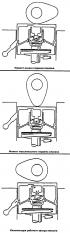
The hydraulic pusher consists of two main moving parts: the pusher itself 2 (see picture), which simultaneously serves as a plunger during operation, and cylinder 4. Under the...
The hydraulic pusher consists of two main moving parts: the pusher itself 2 (see picture), which simultaneously serves as a plunger during operation, and cylinder 4. Under the...
The principle of operation of hydraulic pushers
Starting valve lift At the moment the camshaft cam hits the valve stem, the check valve closes the chamber and the pressure in it increases. An increase in pressure does not...
Starting valve lift At the moment the camshaft cam hits the valve stem, the check valve closes the chamber and the pressure in it increases. An increase in pressure does not...
Checking the technical condition of hydraulic pushers
The design of the hydraulic pusher is non-separable and cannot be repaired. Start the engine and let it run until the cooling fan is turned on for the first time. Maintain the...
The design of the hydraulic pusher is non-separable and cannot be repaired. Start the engine and let it run until the cooling fan is turned on for the first time. Maintain the...
WN Engine Fuel Pump
The fuel pump is fastened with two nuts through a heat-insulating spacer and an o-ring. Pump housing and cover are one-piece, i.e. The design of the fuel pump is non-separable and...
The fuel pump is fastened with two nuts through a heat-insulating spacer and an o-ring. Pump housing and cover are one-piece, i.e. The design of the fuel pump is non-separable and...
Carburetor Pierburg 2B5
Features of the device and calibration data of the Pierburg 2V5 carburetor are given in the subsection « Design and specifications ». The principle of operation of the carburetor...
Features of the device and calibration data of the Pierburg 2V5 carburetor are given in the subsection « Design and specifications ». The principle of operation of the carburetor...
Features of the device and the principle of operation of the system «K-Jetronic»
The fuel pump draws fuel from the fuel tank and delivers it through the filter and accumulator to the fuel distributor. The fuel pump is multistage, rotary. It is driven by a...
The fuel pump draws fuel from the fuel tank and delivers it through the filter and accumulator to the fuel distributor. The fuel pump is multistage, rotary. It is driven by a...

Checking and adjusting the system «K-Jetronic»
Throttle valve adjustment Note. The throttle valve opening is adjusted at the factory and cannot be changed in operation. However, if the stop screw is accidentally turned, the...
Throttle valve adjustment Note. The throttle valve opening is adjusted at the factory and cannot be changed in operation. However, if the stop screw is accidentally turned, the...

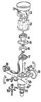
The device and principle of operation of the electronic ignition system
Device The electronic ignition system includes an ignition distributor with a built-in proximity sensor (pulse generator), switch and high energy ignition coil. Like the...
Device The electronic ignition system includes an ignition distributor with a built-in proximity sensor (pulse generator), switch and high energy ignition coil. Like the...


Removal and installation of the sensor-distributor ignition
Removing Disconnect the spark plug wires and ignition coil wire from the ignition distributor. Unfasten the spring clips and remove the cover of the sensor-distributor. Disconnect...
Removing Disconnect the spark plug wires and ignition coil wire from the ignition distributor. Unfasten the spring clips and remove the cover of the sensor-distributor. Disconnect...

Removing and installing the camshaft drive belt
Removing Loosen the alternator mounting bolts and, depending on the configuration, the power steering pump mounting bolts. Remove the alternator drive belt and, depending on the...
Removing Loosen the alternator mounting bolts and, depending on the configuration, the power steering pump mounting bolts. Remove the alternator drive belt and, depending on the...

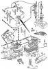
Cylinder head
Removing the cylinder head Disconnect the wire from the negative battery terminal. Drain the fluid from the cooling system by disconnecting the supply hose from the radiator and...
Removing the cylinder head Disconnect the wire from the negative battery terminal. Drain the fluid from the cooling system by disconnecting the supply hose from the radiator and...

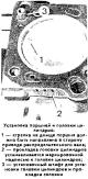
Installing the cylinder head
Clean the removed parts and determine their technical condition by visual inspection. Clean the connector surfaces using suitable detergents. Do not use abrasive materials or...
Clean the removed parts and determine their technical condition by visual inspection. Clean the connector surfaces using suitable detergents. Do not use abrasive materials or...

Disassembly and repair of the cylinder head
When disassembling the cylinder head, put marks on the removed parts in order to put them in their original places during assembly. Remove bearing caps No. 1 and 3 (the reading is...
When disassembling the cylinder head, put marks on the removed parts in order to put them in their original places during assembly. Remove bearing caps No. 1 and 3 (the reading is...

Cylinder head assembly
Install the valve spring support washers and insert the valves into the valve guides. Using a VW 10 204 mandrel, press new valve stem seals onto the valve guides, after putting...
Install the valve spring support washers and insert the valves into the valve guides. Using a VW 10 204 mandrel, press new valve stem seals onto the valve guides, after putting...
Removal and installation of the engine
Removing Disconnect the wire from the negative battery terminal. Remove the hood. Remove the plug from the expansion tank. Disconnect the radiator supply hose from the thermostat...
Removing Disconnect the wire from the negative battery terminal. Remove the hood. Remove the plug from the expansion tank. Disconnect the radiator supply hose from the thermostat...

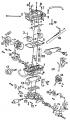
Engine disassembly
Note. When disassembling, put marks on the parts that are suitable for further use, so that during assembly, install them in their original places and in their original position....
Note. When disassembling, put marks on the parts that are suitable for further use, so that during assembly, install them in their original places and in their original position....
Engine Assembly
Checking cylinder diameters Accurately measure cylinder diameters. Measurements to be made with a caliper in three belts as in the transverse direction «A», and in the...
Checking cylinder diameters Accurately measure cylinder diameters. Measurements to be made with a caliper in three belts as in the transverse direction «A», and in the...

Removal and installation of the oil pump
Removing Disconnect the wire from the negative battery terminal. Loosen the alternator mounting bolts and, depending on the configuration, the power steering pump and remove the...
Removing Disconnect the wire from the negative battery terminal. Loosen the alternator mounting bolts and, depending on the configuration, the power steering pump and remove the...
Coolant replacement
There are no holes for draining the coolant from the cooling jacket on engines. Remove the expansion tank cap. Disconnect the coolant supply hose from the thermostat housing and...
There are no holes for draining the coolant from the cooling jacket on engines. Remove the expansion tank cap. Disconnect the coolant supply hose from the thermostat housing and...
Removal and installation of the water pump
Removing Drain the coolant from the system. Set the crankshaft of the engine to the position corresponding to the TDC of the piston of the 1st cylinder. Disconnect the wire from...
Removing Drain the coolant from the system. Set the crankshaft of the engine to the position corresponding to the TDC of the piston of the 1st cylinder. Disconnect the wire from...
This section is available on russian, bulgarian, belarusian, ukrainian, serbian, croatian, romanian, polish, slovak, hungarian
Similar sections from other manuals for VW cars:
Power unit: Engine 1.1/1.3 Volkswagen Golf 1 (1974-1984, petrol)
Power unit: Petrol engines 1.4 (V16) Volkswagen Polo 3 (1995-2003)
Power unit: Petrol engine 4.2L Volkswagen Touareg 1 (2002-2006)
Power unit: Petrol engine 1.4 CAVA Volkswagen Tiguan 1 (2007-2015)
Power unit: Engine repair Volkswagen Transporter T4 (1990-2003)
Petrol engines 1.6 l: Engine repair Volkswagen Caddy 3 (2003-2010)
Passat B6
Passat B5
Passat B4
Passat B3
Passat B2
- General information
- User manual
- Maintenance
- Petrol engine 1.6L
- Engine repair
- Cooling and lubrication system
- Fuel injection system
- Petrol engine 2.0L
- Engine repair
- Lubrication system
- Cooling system
- Fuel and exhaust systems
- Diesel engine 2.0L
- Engine repair
- Cooling and lubrication system
- Fuel and exhaust systems
- Transmission
- Clutch
- Mechanical gearbox
- Automatic gearbox
- Drive shafts
- Chassis
- Wheels and tires
- Car suspension
- Steering
- Brake system
- Body
- Exterior (external elements)
- Electrical equipment
- Power devices
- Lighting and appliances
- Electrical circuits
- General information
- User manual
- Weekly checks
- Maintenance
- Power unit
- Engine repair
- Cooling system
- Fuel system (petrol)
- Fuel system (diesel)
- Engine management
- Exhaust system
- Transmission
- Clutch
- Car gearbox
- Drive shafts
- Chassis
- Car suspension
- Wheels and tires
- Steering
- Brake system
- Body
- Exterior (external elements)
- Interior (internal elements)
- Doors and covers
- Ventilation and heating
- Electrical equipment
- Power devices
- Lighting and appliances
- Electrical circuits
- General information
- User manual
- Maintenance
- Technical data
- 8-valve engine
- Engine repair
- Cooling and lubrication system
- Supply system
- Ignition system
- Fuel injection «Mono-Jetronic»
- Control system «Mono-Motronic»
- Control system «Digifant»
- Control system «Simos»
- 16-valve engine
- Engine repair
- Cooling and lubrication system
- Fuel injection «K-Jetronic»
- Control system «KE-Motronic»
- Control system «Digifant»
- Diesel engine
- Engine repair
- Cooling and lubrication system
- Power and control system
- Turbocharging system
- Digital control system
- Transmission
- Clutch
- Manual gearbox
- Hydromechanical gearbox
- Front wheel drive
- Chassis
- Car suspension
- Steering
- Brake system
- Body
- Body elements
- Electrical equipment
- Power devices
- Lighting and appliances
- Electrical circuits
- General information
- User manual
- Driving Tips
- Maintenance instructions
- Technical data
- Power unit
- Engine repair
- Ignition system
- Lubrication system
- Cooling system
- Supply system
- Petrol injection system
- Diesel engine
- Exhaust system
- Transmission
- Clutch
- Car gearbox
- Chassis
- Suspension
- Steering
- Brake system
- Wheels and tires
- Body
- Exterior
- Interior
- Heating system
- Electrical equipment
- Power devices
- Lighting system
- Equipment and devices
- Wiper system
- Electrical circuits
- General information
- Introduction to instructions
- User manual
- Power unit
- Engines 4-cylinder FZ
- Engines 4-cylinder
- Engines 5-cylinder
- Transmission
- Clutch
- Four-speed gearbox
- Five-speed gearbox
- Hydromechanical gearbox
- Front wheel drive
- Chassis
- Front suspension
- Rear suspension
- Steering
- Brake system
- Body
- Body elements
- Electrical equipment
- Equipment and devices
- Electrical circuits
VWmanual.ru © 2016-2024 | Mobile version | News and articles | Sitemap: EN BG BY UA RS HR RO PL SK HU | Write message | Site search
Passat B2 • Passat B3 • Passat B4 • Passat B5 • Passat B6 • Golf 1, diesel • Golf 1, petrol • Golf 2, petrol • Golf 2 • Golf 3 • Golf 4 • Golf 5 • Polo 3 • Polo 4 • Touareg 1 • Tiguan 1 • Sharan 1 • Transporter T3 • Transporter T4 • Beetle • Caddy 3 •
Passat B2 • Passat B3 • Passat B4 • Passat B5 • Passat B6 • Golf 1, diesel • Golf 1, petrol • Golf 2, petrol • Golf 2 • Golf 3 • Golf 4 • Golf 5 • Polo 3 • Polo 4 • Touareg 1 • Tiguan 1 • Sharan 1 • Transporter T3 • Transporter T4 • Beetle • Caddy 3 •