
Throttle valve adjustment
Note. The throttle valve opening is adjusted at the factory and cannot be changed in operation. However, if the stop screw is accidentally turned, the adjustment is restored as shown below.
Loosen the throttle stop screw (see fig.) and unscrew the screw so that it barely moves away from the stop. Then screw in the stop screw until it touches the stop, then turn it in another half turn.
Tighten the stop screw locknut.
Check engine idle speed and adjust if necessary.
Throttle cable adjustment
Carefully check that there are no bent or twisted sections on the cable.
Press the accelerator pedal all the way down and measure the gap between the throttle control lever and the stop, which should be no more than 1 mm.
Warning. If at least one fold is found on the throttle cable, replace the cable.
Engine idle adjustment
The engine idle speed adjustment is carried out on an engine warmed up to normal operating temperature with a correctly set ignition timing, with a working ignition system, with a clean air filter element.
Check if the throttle valve opening is correctly adjusted.
Make sure that the current consumers are switched off.
Adjusting the engine idling speed
Connect the tachometer according to the instruction manual.
Turn on high beam headlights.
Start the engine and bring the crankshaft speed to 3000 rpm, after 30 seconds, reduce the engine speed to idle, i.e. up to 800-900 rpm.
Note. If the fuel injector lines are disconnected or replaced before adjusting the engine idle, run the engine several times at 3000 rpm and at idle.
If necessary, set the idle speed of the crankshaft within 800-900 rpm with the adjusting screw 1 (see photo), located on the throttle body.
Exhaust CO adjustment
Note. When adjusting the CO content, do not press or pull out the adjusting screw. After installing the socket wrench into the screw head, do not press the accelerator pedal, so as not to damage the adjusting screw.
Connect the gas analyzer according to the operating instructions.
Disconnect the crankcase ventilation hoses.
Remove the plug of the mixture quality adjusting screw located on the fuel dispenser (see photo).
Using a socket wrench for screws with a turnkey socket, turn the mixture quality adjustment screw until the CO content is within 1.0-2.0%.
When the screw is turned clockwise, the CO content in the exhaust gases increases, and vice versa.
If it is necessary to turn the adjusting screw several times in one direction or another in order to achieve the desired CO content, then after each adjustment it is necessary to remove the key and lightly press the accelerator pedal.
After adjustment, put a new plug on the mixture adjustment screw.
After adjusting the engine idle speed, connect the crankcase ventilation hoses.
Checking the performance of the fuel pump
Disconnect the drain hose from the supply pressure regulator on the fuel dispenser and lower its end into a beaker.
Disconnect the high voltage wire from the ignition coil.
Turn on the starter for about 30 seconds and measure the amount of fuel leaked into the beaker, which should be at least 900 cm2.
Note. Replace the fuel line O-rings every time the fuel pump is removed. If the fuel pump does not work, first check the 16 A fuse in the mounting block.
Replace every 15,000 km: fuel filter. When installing a new filter, point the arrow on its housing in the direction of fuel circulation in the system. Never blow out the fuel filter with compressed air.
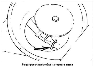
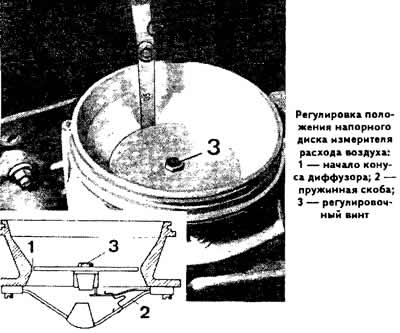
Adjusting the position of the pressure plate of the air flow meter
Make sure that with the engine off, the pressure disc is at the same level or no more than 0.5 mm below the beginning of the expanding cone of the air flow meter diffuser.
If necessary, adjust the position of the pressure plate of the air flow meter by bending the clip 2 with the spring (see photo), after removing the lower housing of the mixture regulator.
Note. If the pressure disk of the air mass meter is above the specified level, backfires occur during misfiring. With the low position of the pressure disk, it is difficult to start both a cold and a hot engine.
Check the centering of the pressure disc by placing a 0.10 mm spacer in succession at four points around the circumference.
If the position of the pressure disc is incorrect, loosen the adjusting screw 3 and center the pressure disc, then tighten the screw 3 to a torque of 0.5 kgf·m.
Adjust engine idle.
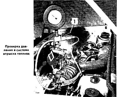
Pressure test
To check the pressure, use a VW 1318 manometer with a fitting and a cock that measures both the flow pressure and the inlet pressure.
Connect the pressure gauge hoses between the distributor and the control pressure supply line from the control pressure regulator.
Remove air pockets from gauge hoses. To do this, start the engine, set the pressure gauge cock to the position to control the flow pressure and lower the pressure gauge so that it hangs freely on the hoses.
Checking the fuel pressure in the system
Check the performance of the fuel pump and the condition of the air filter element.
Set lever 1 (see photo) gauge to position «open», by placing the lever in line with the fitting.
Make sure a shoe is connected to the control pressure regulator.
Start the engine and leave it to idle.
Measure the fuel pressure in the system using the pressure gauge, which should be in the range of 4.7-5.4 kg / cm2.
If the pressure is not within the specified limits, replace the fuel dispenser. You can also try to eliminate the reasons for the deviation of fuel pressure from the required one.
The reasons for insufficient fuel pressure in the system can be:
- leakage of fuel lines and their connections;
- insufficient performance of the fuel pump;
- insufficient fuel supply pressure.
The reason for the increased fuel supply pressure is a violation of the adjustment of the fuel pressure regulator or jamming of its plunger.
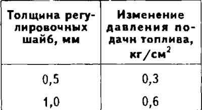
The fuel pressure in the system is regulated by the selection of the thickness of the shims installed on the plunger of the fuel pressure regulator.
Checking the control pressure on a cold engine
Set valve 1 of the manometer to position «closed», placing it perpendicular to the fitting.
Disconnect the block from the control pressure regulator. Disconnect the block from the auxiliary air supply valve.
Start the engine at idle.
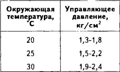
Determine the control pressure on the pressure gauge as a function of the ambient temperature (see table).
If the pilot pressure is not within the specified limits, replace the pilot pressure regulator.
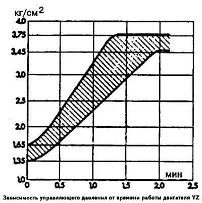
Checking the control pressure on a warm engine
Pilot pressure on a cold engine
Warm up the engine (oil temperature 50-70°C).
Set the pressure gauge valve to position «open».
Connect the block to the control pressure regulator, to the auxiliary air valve.
Start the engine at idle. In this case, the control pressure should increase to 4.05-4.35 kg/cm after 1.3-2.5 minutes.
If the pilot pressure is not within the specified limits, replace the pilot pressure regulator.
Residual pressure test
Warm up the engine (oil temperature 50-70°С).
Stop engine.
Set the pressure gauge valve to position «open».
Start the engine and let it idle until the pressure on the gauge is 4.7-5.4 kg/cm2.
Switch off the ignition. After 10 minutes, the residual pressure in the system should be 2.6 kg/cm2.
If the pressure drops sharply, turn the pressure gauge valve to the position «closed».
Start the engine and let it idle until the gauge shows 4.7-5.4 kg/cm2.
Switch off the ignition. After 10 mn the pressure in the system should be within 2.6 kg/cm2.
The control pressure regulator must be replaced if the pressure decreases with the pressure gauge valve open, but does not decrease with the valve closed.
Checking the fuel pressure at the time of engine shutdown
Warm up the engine (oil temperature 50-70°C).
Install pressure gauge as above.
Set the pressure gauge valve to position «closed».
Measure the fuel pressure in the system, which should be in the range of 4.7-5.4 kg / cm2.
Switch off the ignition.
Measure the fuel pressure in the system at the moment the ignition is turned off, which should drop to 3.0 kg/cm2.
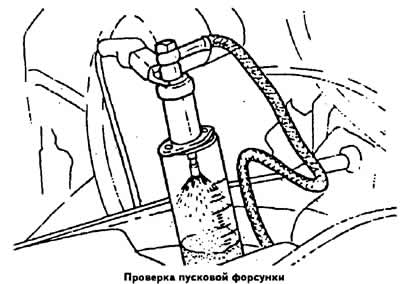
Checking injection nozzles
Unscrew the nozzle from its socket and screw in a spare nozzle instead.
Lower the nozzle into the beaker.
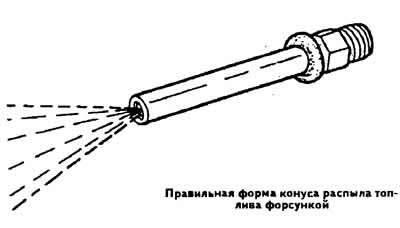
Start the engine, let it run at about 2000 rpm, and check that the fuel injected from the injector is in the shape of a regular cone.
Stop engine. In this case, not a single drop of fuel should appear from the atomizer of the nozzle.
Check the other injectors in the same way.
More accurately, you can check the technical condition of the nozzles using a stand that includes a hand pump and a pressure gauge.
Connect the injector to be tested to the stand according to the operating instructions and check the fuel injection pressure. For a properly working injector, fuel injection should occur at a pressure of 3.0-4.1 kg / cm2.
Check the tightness of the injector. To do this, use the stand pump to create a pressure of 0.5 kg / cm2 less than the fuel injection pressure by the injector, and maintain it for 15 s, during which not a single drop of fuel should flow out of the injector atomizer.
Press the stand pump lever at a frequency of one stroke per second. In this case, fuel should be sprayed from the injector atomizer with a hum in the form of a cone at an angle of approximately 35°.
If the nozzle does not meet at least one of the above requirements, it must be replaced.
Checking the starter injector and thermal time switch
Disconnect the block from the starting injector and connect a test lamp to it.
Disconnect the high voltage wire from the ignition coil.
Turn on starter. On a cold engine (when the coolant temperature is less than 30°С) the control lamp should light up for 1-8 s.
Note. If the test is performed at a higher temperature than that marked on the case of the thermal time relay, the control lamp does not light up.
Check the quality of fuel atomization by the starting injector. To do this, remove the starting nozzle without disconnecting the block and fuel line from it, and place it in a beaker.
Turn on the starter for 1-8 seconds: the starting nozzle should spray fuel in the shape of a regular cone.
Checking the supply voltage of the thermal time relay
Note. The test is carried out at a coolant temperature: liquid below 30°C.
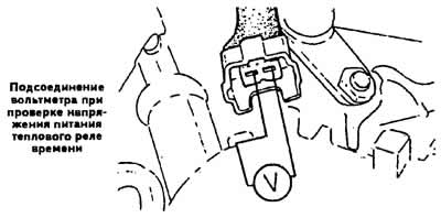
Disconnect the high voltage wire from the ignition distributor and connect it to «weight» body through an extension.
Disconnect the connector from the starting injector and attach a voltmeter to the terminals (see fig.).
Turn on the starter and check the voltage on the voltmeter, which should be 11.5 V.
Pilot pressure regulator test
Warm up the engine (oil temperature 50-70°С).
Disconnect the block from the control pressure regulator and connect a voltmeter to the block.
Turn on the ignition and determine the regulator supply voltage using a voltmeter, which must be at least 11.5 V.
Connect an ohmmeter to the terminals of the regulator and check the resistance of its thermal winding, which should be within 16-22 ohms.
If the ohmmeter reads infinity, this indicates a break in the thermal winding and the control pressure regulator must be replaced.
Checking the auxiliary air valve
On a cold engine (when the coolant temperature is less than 30°С) Disconnect the block from the auxiliary air supply valve.
Disconnect the hose going to the auxiliary air supply valve from the intake manifold.
Connect the tachometer according to the instruction manual.
Start the engine and leave it to idle.
Close the opening of the hose leading to the auxiliary air supply valve. The engine speed should then decrease.
Connect the hose to the intake manifold, connect the block to the auxiliary air supply valve and warm up the engine.
Disconnect the hose leading to the additional air supply valve from the inlet pipe again and close its opening. In this case, the engine speed should not change. If the engine mode changes, replace the auxiliary air valve.
Removal and installation of the block of the batcher-distributor with an air flow meter
Removing
Relieve pressure in the fuel injection line by disconnecting the hose from the control pressure fitting on the fuel pressure regulator.
Disconnect the injector fuel lines from the distributor.
Remove the air line connecting the air flow meter to the throttle body.
Unscrew the mounting bolts of the dispenser-distributor assembly with the air flow meter from the air filter housing and remove the dispenser-distributor and the meter.
If necessary, disconnect the dispenser-distributor from the air flow meter by unscrewing the three bolts on the dispenser-distributor. When doing this, be careful not to drop the control plunger.
Installation
Install the metering unit with the air flow meter on the air filter housing.
Tighten the fixing screws.
Connect the fuel lines to the dispenser-distributor, replacing the gaskets.
Push the connecting air duct onto the air mass meter.
Connect the control pressure line to the fuel pressure regulator with new gaskets.
Adjust engine idle.
Removal and installation of nozzles
Release the fuel injector lines from the holders.
Remove the flange securing the injectors to the engine.
Remove injectors with fuel lines.
Unscrew the pipe fitting from the nozzle.
Remove nozzle.
When installing the injectors, replace the gaskets and moisten the cuffs on the ends of the injectors with gasoline. Install injectors in the reverse order of removal.
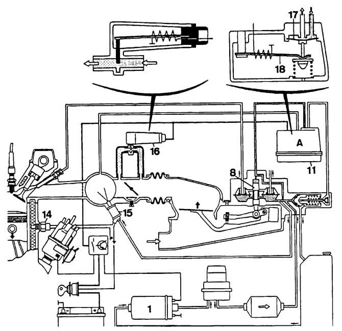
Scheme of the injection system «K-Jetronic» when starting a cold engine:
1 - fuel pump;
8 - distributive plunger of the dispenser-distributor;
11 - control pressure regulator;
14 - coolant temperature sensor;
15 - starting nozzle;
16 - valve for additional air supply;
17 - diaphragm valve for adjusting the control pressure;
18 - bimetallic spring for controlling the control pressure adjustment valve.
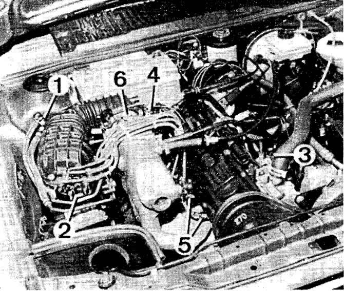
Location of fuel injection system components:
1 - fuel filter;
2 - assembly of the fuel dispenser-distributor and air flow meter;
3 - control pressure regulator;
4 - starting nozzle;
5 - nozzles;
6 - throttle body.
Visitor comments