
The principle of operation of the fuel injection system
The fuel pump draws fuel from the fuel tank and delivers it to the accumulator. Further, the fuel is supplied under pressure through the filter to the fuel dispenser-distributor.
Mounted on a movable arm, the pressure plate of the air flow meter, which is installed between the air filter and the throttle valve, deviates depending on the air depression in the engine. The displacement of the pressure disk of the air flow meter is transmitted to the distribution plunger of the fuel dispenser, thereby determining the amount of fuel supplied. The fuel quantity distributor, depending on the position of the pressure plate of the air flow meter, supplies the required amount of fuel to the engine cylinders through the injectors, ensuring the optimal composition of the fuel-air mixture. The fuel dispenser and air flow meter form a mixture regulator.
The pilot pressure regulator reduces pressure on the control plunger during engine warm-up. Reducing the control pressure at the same air flow leads to an increase in the fuel supply and, consequently, to an enrichment of the combustible mixture.
An additional air supply valve installed in the air duct, made parallel to the throttle valve, brings additional air to the engine during cold start and engine warm-up, which leads to an increase in the engine idle speed.
To facilitate starting a cold engine, an electromagnetic starting nozzle is provided, the opening time of which varies depending on the temperature of the coolant by a thermal time switch.
Air filter
Air filter with replaceable dry filter element. Make and type: Mann 34109/1.
Fuel electric pump
The fuel electric pump is located in the fuel tank in a submerged position.
- Brand and catalog number: Bosch 0 580 254 002.
- Productivity at voltage on outputs of 12 V, l/min: 2.0.
- Consumed current at a voltage of 12 V at the terminals, no more than, A: 8.5.
Fuel storage
The fuel accumulator is installed under the bottom of the body next to the fuel tank on the right.
Brand and catalog number: Bosch 0 438 170 041.
Fuel filter
fuel The second filter is located in the engine compartment.
Brand and catalog number: Bosch 0 450 905 067.
Damper
Brand and catalog number: Bosch 0 280 161 201.
Pilot pressure regulator
Brand and catalog number: Bosch 0 438 140 114.
Resistance of the heating winding of the bimetallic spring of the regulator, Ohm: 16-22.
Fuel dispenser
Brand and catalog number: Bosch 0 438 100 125.
Injection nozzles
Brand and catalog N°: Bosch 0 437 502 024 or 0 437 502 027.
Volume of injected fuel, ml:
- at idle: 3.0;
- at full load: 8.0.
Injection start pressure, kg/cm2: 3,0-4,1.
The maximum allowable pressure difference between the start of injection between 2 injection nozzles, kg/cm2: 0,6.
Starting nozzle
Brand and catalog number: Bosch 0 280 170 400.
Fuel injection duration, s:
- at an outside air temperature of +35°С: 0;
- at an outside air temperature of 0°С: 6.
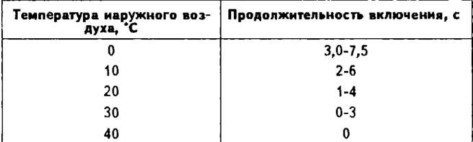
Dependence of the duty cycle on the outside temperature
Air flow meter
Brand and catalog N°: Bosch 0 438 120 186.
Auxiliary air valve
Brand and catalog N°: Bosch 0 280 140 159.
Thermal time switch
Brand and catalog number: Bosch 0 280 130 228.
Positive idle shut-off valve
Brand: VDO.
Working voltage. AT 12.
The valve opens at a crankshaft speed of more than 1200-2000 rpm when the throttle is closed on a warm engine.
Adjustment Data
The frequency of rotation of the crankshaft at idle, rpm: 800-900.
Carbon monoxide content (SO) in exhaust gases at idle,%: 0.5-1.5.
Fuel pressure in the system, kg/cm2:4,7-5,4.
Control pressure, kg/cm2:
- with the vacuum hose of the control pressure regulator connected on a warm engine: 3.4-3.8;
- with the vacuum hose of the control pressure regulator disconnected: 2.75-3.05;
- on a cold engine at a temperature of 20°C: 1.3-1.8.
Residual fuel pressure in the system, kg/cm2:
- 10 minutes after stopping the engine: 2.6;
- 20 minutes after stopping the engine: 2.4.
Visitor comments