
Warm engine idle adjustment
Before adjusting the idle speed, check the correct setting of the ignition timing and the adjustment of the clearances in the valve drive mechanism.
Warm up the engine to operating temperature.
Connect the control tachometer according to the operating instructions.
Set the idle speed of the engine crankshaft within 750-850 rpm by turning the adjusting screw 12 of the mixture amount (see photo).
Connect the gas analyzer according to the operating instructions.
Remove the air filter cover and disconnect the crankcase exhaust ventilation hose.
Check and, if necessary, adjust the CO content with the quality screw (composition) idling mixture in the range of 0.5-1.2%.
Check and, if necessary, readjust the engine idle speed. Repeat these operations until the desired values of the crankshaft speed and CO content are obtained.
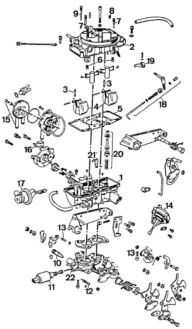
The main details of the Pierburg 2B5 carburetor:
1 - carburetor body;
2 - carburetor cover;
3 - needle valve;
4 - floats;
5 - float chamber gasket;
5 - main fuel jets;
7 - emulsion tubes with fuel and air idle jets;
8 - air jet of the transition system of the 2nd chamber;
9 - air jet of the transition system of the 1st chamber;
10 - adjusting bandage of the amount of idle mixture;
11 - electromagnetic shut-off valve;
12 - quality adjustment bandage (composition) idle mixtures;
13 - restrictive bandage of throttle valves;
14 — throttle actuator of the 2nd chamber;
15 - automatic starting device;
16 - protective cap;
17 - pneumatic actuator of the air damper;
18 - accelerator pump drive;
19 — a pusher of a rod of the piston of the accelerator pump;
20 - accelerator pump;
21 - spray accelerator pump;
22 - throttle body.
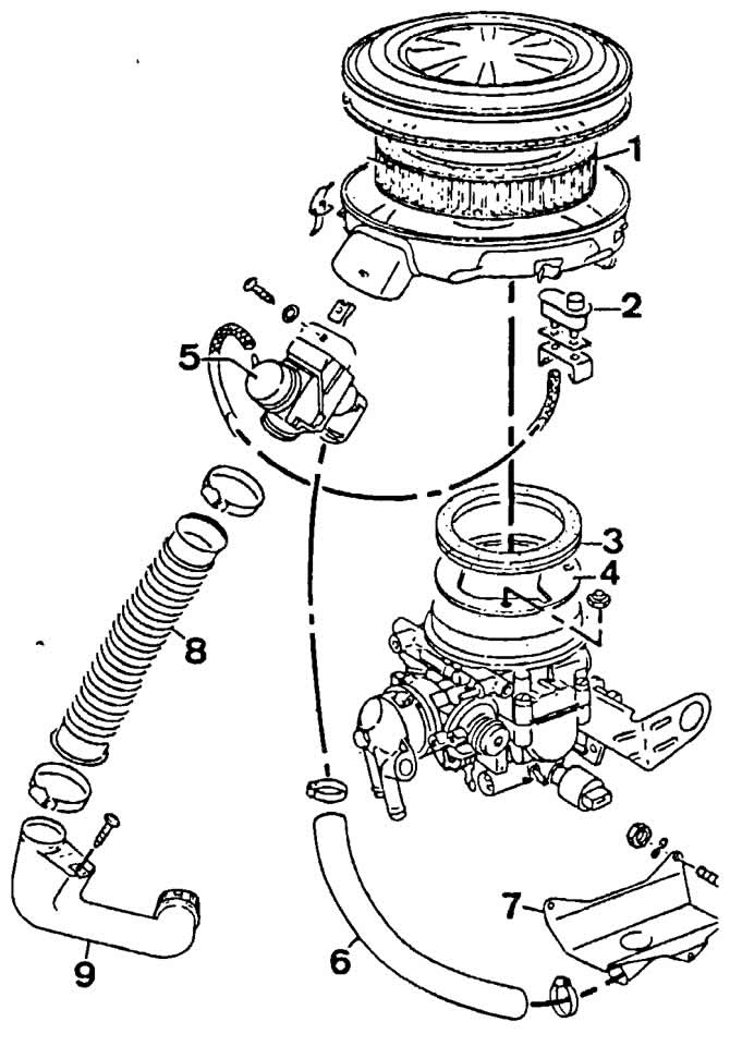
Air filter details:
1 - filter element;
2, 5 - thermostats;
3 - gasket;
4 - bracket;
6 - a hose for supplying warm air;
7 — damper of warm air;
8 - connecting hose;
9 - air intake pipe.
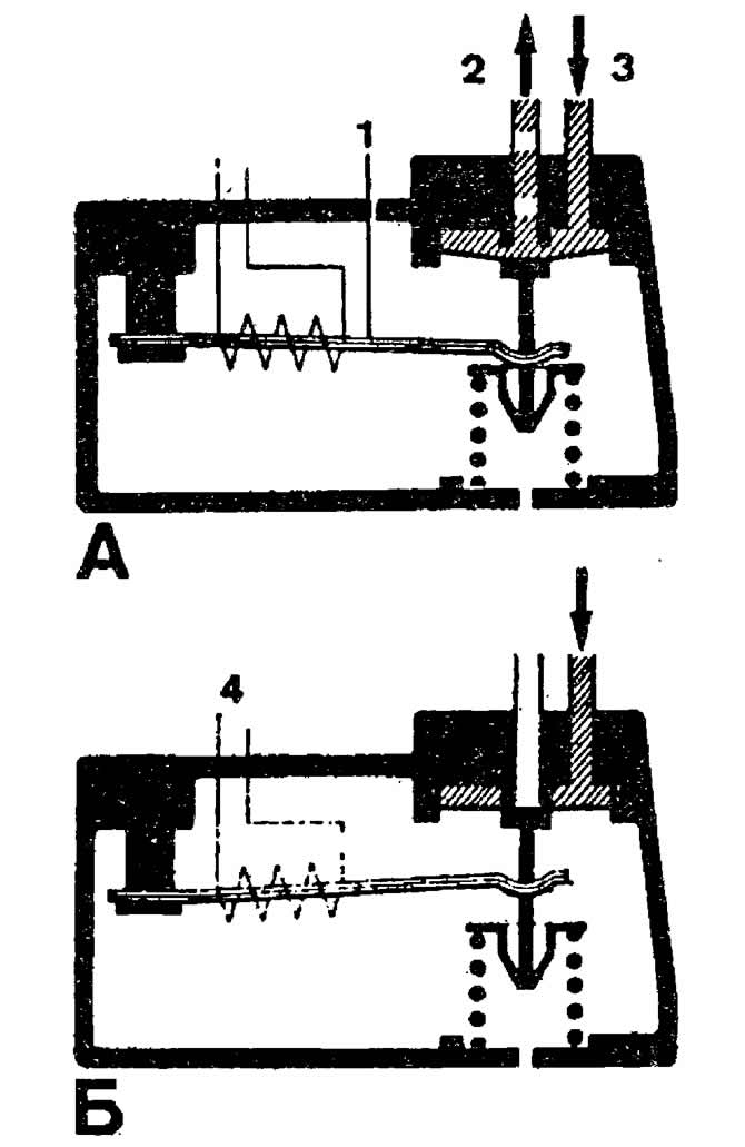
Operating principle of the control pressure regulator:
A - on a cold engine;
B - on a hot engine.
1 - bimetallic spring;
2 - fuel drain;
3 - control pressure supply;
4 - thermal winding of a bimetallic spring.
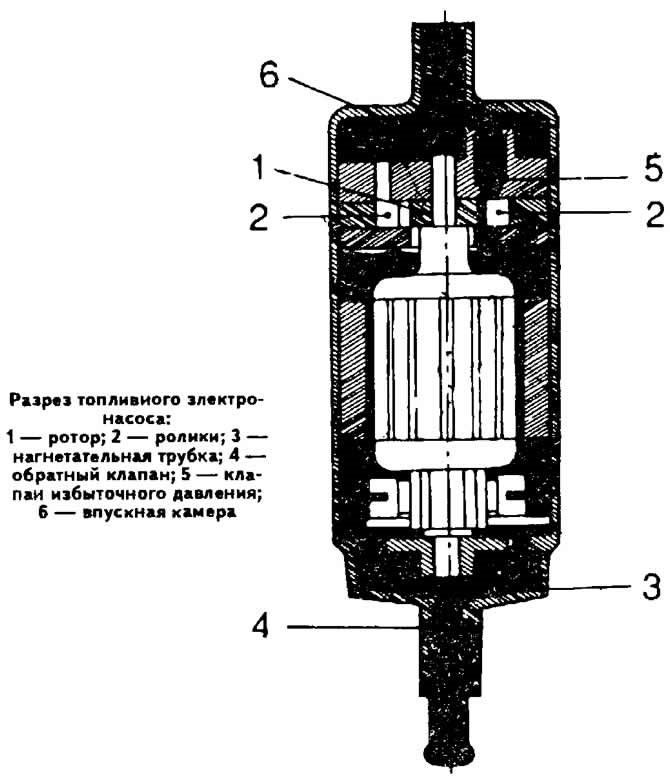
Section of the fuel electric pump:
1 - rotor;
2 - rollers;
3 - injection tube;
4 - check valve;
5 - overpressure valve;
6 - inlet chamber.
Visitor comments