
Increased idle speed
1. Attach a tachometer to the engine.
2. Plug the air filter thermostat vacuum hose (air filter removed).
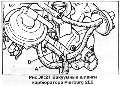
3. Remove the tee (A) from the vacuum hose (IN) - pic. F:21 - and plug the hose.
4. Start the engine and measure the over idle speed.
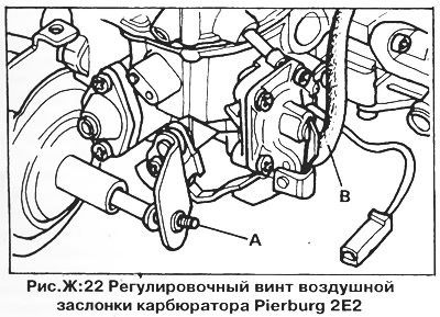
5. If the idle speed is outside the limits specified in section "Technical data", adjust them by turning the adjusting screw (Ah, fig. F:22).
6. Connect the vacuum hose, if necessary, adjust the idle speed (see chapter "Engine adjustment").
7. Lock the adjusting screw (A) paint.
Start throttle position (basic adjustment) - Primary chamber.
The position of the throttle stop screw is set at the factory and should not be changed. The initial throttle position should only be adjusted if the screw position has been changed.
1. Turn the warm-up control cam (Ah, fig. F:23) so that the pin (IN) on the throttle lever did not touch the cam.

2. Fix the cam in this position with a screwdriver (D), by inserting it between the cam and the lever (WITH).
3. Remove the hoses from the three nozzles of the vacuum drive and plug the nozzles (B, fig. F:24).
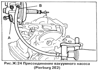
4. Connect the vacuum pump to the nozzle (Ah, fig. F:24) and create the vacuum necessary to hold the diaphragm in the closed throttle position.
5. Make sure there is a gap between the high idle adjustment screw and the diaphragm pusher.
6. Loosen the stop screw (Ah, fig. F:25) so that between it and the throttle limiter (B, fig. F.25) there was a gap.
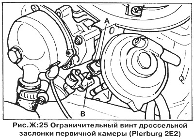
7. Tighten the screw until it touches the stop.
8. Turn the adjusting screw an additional 1/4 turn and seal its threads with paint.
Start throttle position (basic adjustment) - secondary chamber.
The throttle position is set at the factory and should not be changed. The initial throttle position should only be adjusted if the setting has been changed.
1. Remove the carburetor as described earlier in this chapter.
2. Fully open the throttle valve of chamber I and firmly fix it in this position (Ah, fig. F:28).
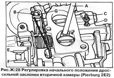
3. Use a rubber band to tighten the camera throttle lever AND (B, fig. F:28).
4. Remove the stop screw (WITH) so that there is a gap between the screw and the stop (D, fig. F:28).
5. Screw in the stop screw until it touches the stop.
6. Tighten the stop screw an additional 1/4 turn.
7. Release both throttles and check the clearance in the damper drive mechanism (E and F, fig. F:28).
8. Adjust the gap by bending the lever (shown by arrow), if the gap value is outside the limits specified in section "Technical data".
Choke Starting Gap - Stage 1
1. Remove the auto choke cover.
2. Turn the choke lever clockwise and secure it in this position with a rubber band.
3. Remove the vacuum hose from the carburetor and attach a vacuum pump instead (B, fig. G:22 and A, fig. F:24).
4. Remove the vacuum hose (C, fig. F:26), but don't mute it.

5. Create and maintain a vacuum of 200-300 mbar.
6. Check the choke gap with a drill shank of the correct diameter (D, fig. F:26).
7. If the gap is outside the limits specified in section "Technical data", adjust it with an Allen screw (B, fig. F:26). Lock the adjusting screw with paint.
Choke Starting Gap - Stage 2
1. Plug the vacuum hose (E, fig. F:26).
2. Create a vacuum of 200 mbar using a vacuum pump.
3. Check the choke gap with a drill (B, fig. F:27).
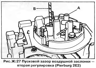
4. If the gap is outside the limits specified in section "Technical data", adjust it with a screw (C, fig. F:27).
5. Lock the screw with paint.
Air damper housing and cover alignment
The marks on the body and cover of the air damper actuator must be aligned.
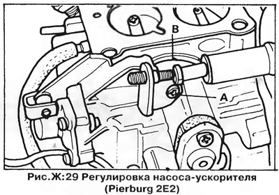
Accelerator pump
1. Connect the vacuum pump to the vacuum drive connector (Ah, fig. F:24).
2. Plug the open connection of the vacuum drive (B, fig. F:24).
3. Apply the vacuum needed to hold the diaphragm in the closed throttle position. There must be an air gap between the high idle adjusting screw and the diaphragm pusher.
4. Rotate the warm-up control lever so that the throttle lever pin is not touching it.
5. Fix the warm-up control lever in this position by inserting an M8x20 bolt between the lever and the carburetor body.
6. Install a measuring container under the mixing chamber of the carburetor to collect fuel.
7. Open and close the throttle five times within 15 seconds.
8. Measure the amount of fuel that entered the container, divide this value by 5 and compare the obtained value with that indicated in section "Technical data".
9. If the pump capacity is not within the specified limits, loosen the clamping screw (Ah, fig. F:29) and adjust the pump by turning the cam (IN) increased idle speed. After adjustment, install the carburetor on the engine and check the idle speed and CO content (see "Engine adjustment").
Visitor comments