
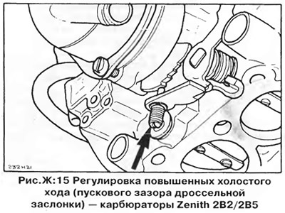
Increased idle speed
1. Attach a tachometer to the engine (see chapter "Engine adjustment").
2. Open throttle, close choke fully, then release throttle. The high idle adjusting screw must be on the highest step of the cam (pic. F:15).
3. Start the engine without touching the accelerator pedal and note the high idle speed.
4. If the value obtained is outside the limits specified in the section "Technical data", remove the protective plug and adjust the speed with the adjusting screw (pic. F:15).
Air damper starting clearance (2B2)
1. Remove the automatic choke actuator cover without disconnecting the electric heater wire or cooling system hoses from the cover.
2. Open the throttle and turn the high idle cam (on the back of the air damper housing) so that the adjusting screw is at the top of the cam. Screwdriver push diaphragm rod (Ah, fig. F:16) as far as it will go and secure the choke lever with a rubber band (B, fig. F:16).
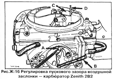
3. Lightly press the choke (C, fig. F:16), to select the backlash in the mechanism, and measure the gap between the lower edge of the air damper and the wall of the carburetor mixing chamber using a drill of the appropriate diameter (D, fig. F:16) - see section "Technical data".
4. Adjust the gap by turning the stop screw on the diaphragm body (pic. F:17).
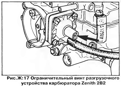
Reinstall the air damper cover; The mark on the cover must be aligned with the mark on the body.
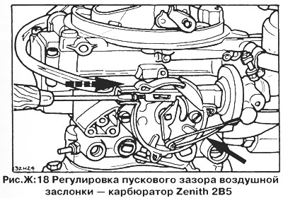
Air damper starting clearance (2B5)
The choke start clearance is adjusted in the same way as on the 2B2 carburetor, but the adjusting screw is at the end of the diaphragm rod (pic. F:18).
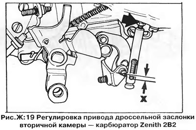
Secondary chamber throttle actuator
The throttle valve of the secondary chamber is controlled by a vacuum diaphragm, to which it is connected by a short rod. On the 2B5 carburetor, this device is made of plastic, the thrust is not adjustable. On the 2B2 carburetor, the rod is metal and can be adjusted.
On early models, adjust the actuator as follows: Disconnect the lower end of the link from the ball stud on the secondary throttle lever. The lower edge of the hole in the rod should be 1-2 mm below the center of the ball head of the pin ("X", pic. F:19). To adjust the linkage, loosen the locknut on the top of the linkage and rotate the linkage until the hole is in the correct position relative to the pin, then tighten the locknut. Connect the link to the secondary throttle lever.
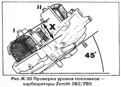
Float level
To check the float level, remove the carburetor cover by disconnecting the choke rod. After replacing the cover, check the air damper adjustment.
Turn the carburetor cap over, rotate it at an angle of 45° (pic. F:20) and measure the distance from the farthest point of each float to the surface of the cap (the spring-loaded pin of the needle valve must not be pressed). Data for adjusting the floats are given in the section "Technical data".
To carry out this check, it is convenient to make a template of appropriate dimensions from rigid cardboard or similar material.
Adjustment is carried out by bending the tongue on the float lever (with the float removed).
Thermal switches
The 2B5 carburetor has the same thermal switch block as the 1B3 carburetor. The thermal switches control the electric heaters for the automatic choke actuator and the intake manifold. The check is carried out in the same way as for the 1B3 carburetor.
The 2B2 carburetor has only one thermal switch that controls the auto choke heater. The operating temperature of this thermal switch is 30°C.
Visitor comments