



Golf 1 (1974-1984, diesel)
Golf 1 (1974-1984, petrol)
Golf 2 (1984-1993, petrol)
Golf 2 (1984-1993)
Golf 3 (1991-1997)
Golf 4 (1997-2004)
Golf 5 (2003-2008)
Vehicle body and equipment VW Golf 2, petrol

Front buffer
1. Disconnect the turn signal light connectors. 2. Unscrew the bolts shown by the arrows in photo 11.1, securing the buffer bracket to the left and right side members of the body....
1. Disconnect the turn signal light connectors. 2. Unscrew the bolts shown by the arrows in photo 11.1, securing the buffer bracket to the left and right side members of the body....

Radiator protection
Disassembly 1. Open the engine cover. 2. Use a small screwdriver to lightly push down the center portion of each of the top tabs on the plastic heatsink guard while pulling the...
Disassembly 1. Open the engine cover. 2. Use a small screwdriver to lightly push down the center portion of each of the top tabs on the plastic heatsink guard while pulling the...

Front end
1. Remove the front buffer. 2. Remove the plastic radiator protection. 3. Unscrew and remove the lower plastic connector 8, see fig. 11.1, which is secured with nine hex head...
1. Remove the front buffer. 2. Remove the plastic radiator protection. 3. Unscrew and remove the lower plastic connector 8, see fig. 11.1, which is secured with nine hex head...

Mounting the front
10. Attach the front part to the body and screw tightly. 11. Screw the right radiator bracket with rubber-metal element from above and insert the central bracket into the socket...
10. Attach the front part to the body and screw tightly. 11. Screw the right radiator bracket with rubber-metal element from above and insert the central bracket into the socket...

Rear buffer
1. Unscrew the bolt 1 that fastens the buffer bracket on the right and left sides of the car to the floor plate, shown by arrows in photo 11.10. 2. Slide the buffer out of the...
1. Unscrew the bolt 1 that fastens the buffer bracket on the right and left sides of the car to the floor plate, shown by arrows in photo 11.10. 2. Slide the buffer out of the...

Replacing the buffer pad
1. Take out the buffer. 2. Separate the plastic cover from the steel profile of the buffer by lifting it with a screwdriver. 3. Using a hand press, press the steel profile of the...
1. Take out the buffer. 2. Separate the plastic cover from the steel profile of the buffer by lifting it with a screwdriver. 3. Using a hand press, press the steel profile of the...

Front fender disassembly
1. Loosen the bolts securing the wheel, raise and support the front of the car on stands. Remove wheel. 2. Take out the front buffer. 3. Remove the protection of the arch. 4...
1. Loosen the bolts securing the wheel, raise and support the front of the car on stands. Remove wheel. 2. Take out the front buffer. 3. Remove the protection of the arch. 4...

Disassembly and assembly of the wheel hub
1. Loosen the bolts securing the wheel, lift and support the front of the car on stands, remove the wheel. 2. Loosen the screws securing the rim (photo 11.11) taking them out...
1. Loosen the bolts securing the wheel, lift and support the front of the car on stands, remove the wheel. 2. Loosen the screws securing the rim (photo 11.11) taking them out...

Pipelines that drain water from the roof
Cleaning Cars with a sliding roof have a piping system. draining water from the slit of the lid. Clogged pipelines are best pierced with an old flexible speedometer drive cable....
Cleaning Cars with a sliding roof have a piping system. draining water from the slit of the lid. Clogged pipelines are best pierced with an old flexible speedometer drive cable....

Roof eaves
Removing 1. Unfasten the outer lip of the gasket. 2. Raise the end of the roof eaves. 3. Unfasten the following latches by inserting a suitably bent rigid steel wire under the...
Removing 1. Unfasten the outer lip of the gasket. 2. Raise the end of the roof eaves. 3. Unfasten the following latches by inserting a suitably bent rigid steel wire under the...

Side decorative cornice
In models up to August 1989, the side decorative cornices were glued to the body. Before dismantling, the cornice must be heated with a stream of hot air until the adhesive...
In models up to August 1989, the side decorative cornices were glued to the body. Before dismantling, the cornice must be heated with a stream of hot air until the adhesive...

External door handle
Disassembly 1. Use a screwdriver to pry up the front edge of the decorative cover of the handle (photo 11.13). 2. Unscrew the two screws with cross-shaped slots that secure the...
Disassembly 1. Use a screwdriver to pry up the front edge of the decorative cover of the handle (photo 11.13). 2. Unscrew the two screws with cross-shaped slots that secure the...

Central blocking of door locks
The central door locking system consists of a pump driven by an electric motor and pipelines supplying air to individual locking actuators. The interlock pump is a double acting...
The central door locking system consists of a pump driven by an electric motor and pipelines supplying air to individual locking actuators. The interlock pump is a double acting...
Door lock
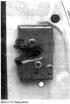
Removing the lock 1. Unscrew the two fixing bolts and move the lock a little (photo 11.17). 2. Insert a screwdriver through the hole in the lock indicated by the arrow in photo...
Removing the lock 1. Unscrew the two fixing bolts and move the lock a little (photo 11.17). 2. Insert a screwdriver through the hole in the lock indicated by the arrow in photo...

External rear view mirror
Golf and Jetta vehicles are equipped with several types of rear-view mirrors, from conventional to electrically controlled mirrors. 1. The outer mirror, shown in photo 11.19, is...
Golf and Jetta vehicles are equipped with several types of rear-view mirrors, from conventional to electrically controlled mirrors. 1. The outer mirror, shown in photo 11.19, is...

Door lining
On fig. 11.6 presents the elements of the door lining. Pic. 11.6. door lining 1 - handle cover; 2 - handle; 3 - bolt; 4 - inner door handle; 5 - screws; 6 - pocket; 7 - facing; 8...
On fig. 11.6 presents the elements of the door lining. Pic. 11.6. door lining 1 - handle cover; 2 - handle; 3 - bolt; 4 - inner door handle; 5 - screws; 6 - pocket; 7 - facing; 8...

Front door
The components of the door after removing the inner lining are shown in fig. 11.7. Pic. 11.7. Front door 1 - door stop; 2 - inner glass lining; 3 - outer glass gasket; 4 - outer...
The components of the door after removing the inner lining are shown in fig. 11.7. Pic. 11.7. Front door 1 - door stop; 2 - inner glass lining; 3 - outer glass gasket; 4 - outer...

Dismantling the interior door handle
1. Remove the door lining. 2. Remove the seal 15 of the inner door handle 16, see fig. 11.7 Pic. 11.7. Front door 1 - door stop; 2 - inner glass lining; 3 - outer glass gasket; 4...
1. Remove the door lining. 2. Remove the seal 15 of the inner door handle 16, see fig. 11.7 Pic. 11.7. Front door 1 - door stop; 2 - inner glass lining; 3 - outer glass gasket; 4...

Manual glass lifting mechanism
Removing 1. Remove the inner lining of the door. Carefully peel off the protective foil 2. Lower the glass and turn away from the lift (photo 11.25). Move glass up. 3. Unscrew the...
Removing 1. Remove the inner lining of the door. Carefully peel off the protective foil 2. Lower the glass and turn away from the lift (photo 11.25). Move glass up. 3. Unscrew the...

Door glass
Disassembly 1. Take out the inner lining of the door. 2. Remove protective foil. 3. Lower the glass, turn away from the lift and lower it down. 4. In cars manufactured before July...
Disassembly 1. Take out the inner lining of the door. 2. Remove protective foil. 3. Lower the glass, turn away from the lift and lower it down. 4. In cars manufactured before July...
Body side glass replacement
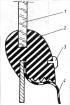
Attention: In the Golf 60 and Golf Rallye, the side windows are glued to the body and cannot be replaced using the method described below. 1. If an old gasket is used to install...
Attention: In the Golf 60 and Golf Rallye, the side windows are glued to the body and cannot be replaced using the method described below. 1. If an old gasket is used to install...
Removing and installing the front seat
1. Raise the hook at the back of the camouflage rail on the rail. 2. Slide the camouflage rail with the guide towards the rear of the vehicle. 3. Move the seat forward. 4. To turn...
1. Raise the hook at the back of the camouflage rail on the rail. 2. Slide the camouflage rail with the guide towards the rear of the vehicle. 3. Move the seat forward. 4. To turn...

Trunk lid
The trunk lid of the car is attached to the body on canopies and is supported in the open position by gas springs (photo 11.28). To remove the trunk lid, do the following: 1....
The trunk lid of the car is attached to the body on canopies and is supported in the open position by gas springs (photo 11.28). To remove the trunk lid, do the following: 1....

Heating
The car interior is heated in an intermediate way. The coolant heated in the engine flows through pipelines to the stove. The air flowing through the stove is heated, and then it...
The car interior is heated in an intermediate way. The coolant heated in the engine flows through pipelines to the stove. The air flowing through the stove is heated, and then it...

Front window wiper
The front window wiper assembly consists of an electric motor 8 (pic. 11.13) with gear, lever system 5 and wiper arms 2 All parts are attached to the bracket 6. The wipers are...
The front window wiper assembly consists of an electric motor 8 (pic. 11.13) with gear, lever system 5 and wiper arms 2 All parts are attached to the bracket 6. The wipers are...

Rear window wiper
Electric motor with gear 13 (photo 11.33), fixed on the bracket 14. Through the lever system 12 and the axis 11, the electric motor drives the rear wiper arm 3 and the feather 2...
Electric motor with gear 13 (photo 11.33), fixed on the bracket 14. Through the lever system 12 and the axis 11, the electric motor drives the rear wiper arm 3 and the feather 2...

Glass sprinkler
The sprinkler pump 9 is fixed on the tank 11 and is driven by advancing the wiper lever located on the right side towards the steering wheel (photo 11.35). The liquid from the...
The sprinkler pump 9 is fixed on the tank 11 and is driven by advancing the wiper lever located on the right side towards the steering wheel (photo 11.35). The liquid from the...

Dividing board
Removing the separation board requires the following steps: 1. Disconnect the battery clamp with the sign so as not to cause an electrical circuit during operation. 2. Loosen the...
Removing the separation board requires the following steps: 1. Disconnect the battery clamp with the sign so as not to cause an electrical circuit during operation. 2. Loosen the...
This section is available on russian, bulgarian, belarusian, ukrainian, serbian, croatian, romanian, polish, slovak, hungarian
Golf 5
Golf 4
Golf 3
Golf 2
Golf 2 (petrol)
Golf 1 (petrol)
Golf 1 (diesel)
- General information
- User manual
- Maintenance
- Troubleshooting
- Power unit
- Engine repair
- Cooling and ventilation system
- Fuel system
- Ignition system
- Transmission
- Clutch
- Mechanical gearbox
- Automatic gearbox
- Chassis
- Brake system
- Car suspension
- Steering
- Body
- Interior (internal elements)
- Exterior (external elements)
- Doors and covers
- Electrical equipment
- Power devices
- Washers and wipers
- Lighting and appliances
- Electrical circuits
- General information
- User manual
- Weekly checks
- Maintenance
- Power unit
- Petrol engines
- Diesel engines
- Cooling system
- Fuel system (petrol)
- Control system (petrol)
- Fuel system (diesel)
- Exhaust system
- Transmission
- Clutch
- Car gearbox
- Drive shafts
- Chassis
- Car suspension
- Steering
- Wheels and tires
- Brake system
- Body
- Exterior (external elements)
- Interior (internal elements)
- Ventilation and heating
- Car doors and sunroof
- Washers and glass cleaners
- Electrical equipment
- Power devices
- Lighting and appliances
- Electrical circuits
- Petrol engine
- Engine repair
- Lubrication system
- Cooling system
- Ignition system
- Diesel engine
- Engine repair
- Diesel injection system
- Pre-glow system
- Transmission
- Clutch
- Gearbox and drive shafts
- Chassis
- Steering
- Wheels and suspension
- Brake system
- Electrical equipment
- Lighting and appliances
- Electrical circuits
- General information
- Introduction to guide
- User manual
- Petrol engines 1.3 l
- Engine repair
- Lubrication system
- Cooling system
- Carburetors
- Supply system
- Ignition system
- Petrol engines 1.6/1.8 l
- Engine repair
- Supply system
- Ignition system
- Diesel engines
- Engine repair
- Lubrication system
- Cooling system
- Power and exhaust system
- Transmission
- Clutch
- 4-speed gearbox 084
- 5-speed gearbox 085
- 4-speed gearbox 020/4R
- 5-speed gearbox 020/4T
- Automatic gearbox
- Drive shafts
- Chassis
- Steering
- Car suspension
- Brake system
- Body
- Body elements
- Doors, locks and windows
- Electrical equipment
- Equipment and devices
- Power devices
- General information
- Characteristics
- Car care
- Maintenance
- Power unit
- Engine repair
- Engine 1.05/1.30
- Engine 1.60/1.80
- Cooling and lubrication system
- Power and exhaust system
- Transmission
- Clutch
- Car gearbox
- Drive shafts
- Chassis
- Brake system
- Steering
- Suspension
- Body
- Body and equipment
- Electrical equipment
- Lighting and appliances
- Electrical circuits
- General information
- Characteristics
- User manual
- Maintenance
- Power unit
- Engine adjustment
- Engine 1.1/1.3
- Engine 1.5/1.6/1.8
- Engine electrical equipment
- Cooling system
- Fuel system
- Transmission
- Clutch and manual gearbox
- Automatic gearbox
- Chassis
- Steering
- Front suspension
- Rear suspension
- Brake system
- Electrical equipment
- Lighting and appliances
- Electrical circuits
- Body
- Body and equipment
- Optional equipment
- General information
- Specifications
- Maintenance
- Power unit
- Engine repair
- Exhaust and turbocharger
- Cooling system
- Fuel system
- Fuel injection system
- Transmission
- Clutch and drive shafts
- Car gearbox
- Chassis
- Suspension and wheels
- Steering
- Brake system
- Wheels and tires
- Body
- Heating and ventilation
- Exterior (external elements)
- Interior (internal elements)
- Doors and windows
- Electrical equipment
- Equipment and devices
- Lighting system
- Power devices
- Electrical circuits
VWmanual.ru © 2016-2024 | Mobile version | News and articles | Sitemap: EN BG BY UA RS HR RO PL SK HU | Write message | Site search
Passat B2 • Passat B3 • Passat B4 • Passat B5 • Passat B6 • Golf 1, diesel • Golf 1, petrol • Golf 2, petrol • Golf 2 • Golf 3 • Golf 4 • Golf 5 • Polo 3 • Polo 4 • Touareg 1 • Tiguan 1 • Sharan 1 • Transporter T3 • Transporter T4 • Beetle • Caddy 3 •
Passat B2 • Passat B3 • Passat B4 • Passat B5 • Passat B6 • Golf 1, diesel • Golf 1, petrol • Golf 2, petrol • Golf 2 • Golf 3 • Golf 4 • Golf 5 • Polo 3 • Polo 4 • Touareg 1 • Tiguan 1 • Sharan 1 • Transporter T3 • Transporter T4 • Beetle • Caddy 3 •