



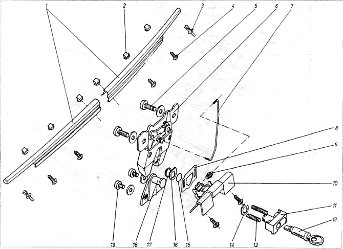
Figure 11.10. Stove control rods
1 - heater valve cable; 2 - valve cable directing air to the middle and sides; 3 - cable of the valve directing air to the window and legs; 4 - body; 5 - controls; 6 - plastic ends; 7 - Dividing board; 8 - screws; 9 - lid; 10 - rotary handle.
The heating intensity and air direction are adjusted using control rods, see Figures 11.10 and 11.11.
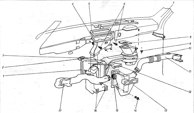
Figure 11.11. Stove
1 - stove; 2 - pipelines supplying warm water and return; 3 - heater valve; 4 - air supply pipeline to the window; 5 - gasket; 6 - bolts; 7 - body; 8 - gasket; 9 - nut; 10 - Blower; 11 - air supply pipe, right; 12 - control rods; 13 - air outlet manifold to the middle, left and right; 14 - nut; 15 - gasket; 16 - air outlet to the legs; 17 - air supply pipe, left.
One lever controls the flow of cold air, and the other - the air duct passing through the stove. By moving both levers to the appropriate position, the air can be mixed.
The original article is available at www.vwmanual.ru
Warm air is mixed with cold air in the appropriate proportion and thus the desired temperature inside the car is achieved.
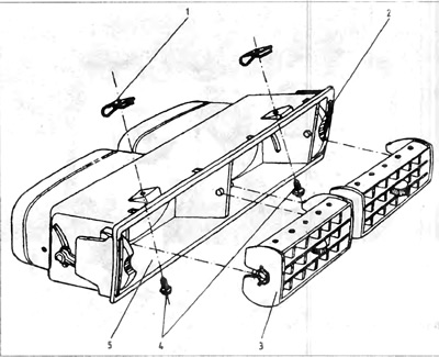
Figure 11.12. Air supply
1 - hooks; 2 - damper control wheel; 3 - cell; 4 - fastening screws; 5 - body.
Visitor comments