
English Русский
Български
Беларускі
Український
Српски
Hrvatski
Română
Polski
Slovenský
Magyar
  |  Articles  |  Sitemap  |  Contacts  |    |
Car maintenance Ford Car maintenance Hyundai Car maintenance Chevrolet Car maintenance BMW Car maintenance Audi Car maintenance Opel Car maintenance AvtoVAZ
VWmanual.ru


Main   Passat   Golf   Polo   Touareg   Tiguan   Sharan   Transporter   Others  
Golf 1 (1974-1984, diesel) Golf 1 (1974-1984, petrol) Golf 2 (1984-1993, petrol) Golf 2 (1984-1993) Golf 3 (1991-1997) Golf 4 (1997-2004) Golf 5 (2003-2008)

Solex PICT/PIC carburetors (VW Golf 1)

  • Main
  • Golf
  • Golf 1
  • Power unit
  • Fuel system
  • Solex PICT/PIC carburetors
            0


Contents: Adjusting high idle speed ↓ Air damper starting clearance ↓ Fuel shut-off valve ↓ Throttle body heater ↓
Adjustment of idle speed and CO content in exhaust gases is described in the chapter "Engine adjustment". Remove the air filter, then adjust the carburetor in the following order:

Adjusting high idle speed


1. Connect a tachometer to the engine (see chapter "Engine adjustment").

2. On 1.1 and 1.3 l engines (since August 1979) with manual choke, adjust the choke cable as described above.

3. Pull the air damper control knob out fully and push it back to the first detent position.

4. Open the air damper by hand by turning the damper shaft (figure W:9). Start the engine and note the high idle speed value on the tachometer.
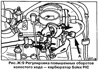
4. Open the air damper by hand by turning the damper shaft (figure W:9). Start the engine and note…


5. If the value of increased idle speed goes beyond the specified limits (see section "Technical data"), remove (if available) safety cap and adjust the high idle speed by turning the throttle stop screw (A, figure W:9).

On engines with automatic choke, start the engine and set the throttle stop screw to the third stage of the high idle cam (A, figure W:10). If the high idle speed value is outside the specified limits (see section "Technical data"), remove the protective cap and adjust the idle speed by turning the limit screw. There should be a gap of at least 0.2 mm between the end of the limit screw and the high idle speed cam with the air damper fully open (B, figure W:10).
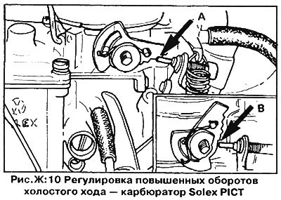


On engines with automatic choke, start the engine and set the throttle stop screw to the third…


Air damper starting clearance


1. On Solex PIC carburetors with manual choke, pull the choke control knob all the way out until the high idle cam is in the highest position. Remove the bimetallic spring cover from the choke actuator housing

2. On Solex PICT carburetors with an automatic choke, remove the bimetallic spring cover with the water box from the automatic choke housing and close the choke.

3. Press the air damper relief device diaphragm rod until it stops against the diaphragm housing (figure W:11).
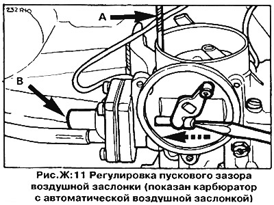
3. Press the air damper relief device diaphragm rod until it stops against the diaphragm housing…


4. Check the gap size between the upper edge of the air damper and the wall of the mixing chamber using a drill shank of the appropriate diameter (A, figure W:11) — see section "Technical data".


5. Adjust the gap if it is not within the specified limits by turning the limit screw in the diaphragm housing (B, figure W: 11).

6. Replace the bimetallic spring cover. Make sure that the bimetallic spring engages with the air damper lever. The mark on the cover should align with the mark on the carburetor body.

Fuel shut-off valve


The electromagnetic shut-off valve of the fuel supply cut-off serves to close the bypass (bypass) channel of the idle speed when the ignition is turned off in order to prevent further operation of the engine (the so-called "anti-diesel"). The valve is screwed into the side surface of the carburetor body under the idle speed adjustment screws.

When the ignition is turned on, the valve operates with a clearly audible click. When removing the valve, the plunger should be recessed inward by 3-4 mm. If the valve does not work, replace it.

Throttle body heater


On models with 1.1/1.3 l engines (since July 1978) a carburetor with an electric heating element is installed, which serves to heat the throttle valve area. The heater is located under the air valve body next to the accelerator pump.

To test the heating element, disconnect its wire from the connector on the top of the carburetor, then connect a test light between the terminal of the heating element and the positive terminal of the battery. The light should light, otherwise replace the heating element.

This article is available at russian, bulgarian, belarusian, ukrainian, serbian, croatian, romanian, polish, slovak, hungarian
The text has been checked: Tarasov Ivan

Share information:

Previous articles
Removal and installation the carburetor
Carburetor drive
Air filter
Fuel pump
Tools and equipment
General information about the fuel system
Next articles
Carburetors Pierburg/Zenith 1B3
Zenith 2B2/2B5 Carburetors
Carburetor Pierburg 2E2
Fuel injection system
Removal and installation the fuel tank
Possible malfunctions of the fuel system


Similar articles from other manuals for VW cars:
Technical characteristics of carburetors Passat B2 (1981-1988)
Carburetor 34 PICT — design description Transporter T3 (1979-1992)
Link to this page in different formats


Visitor comments


No comments yet


How much will 36 + 27 =


Golf 5 
  • General information
  • User manual
  • Maintenance
  • Troubleshooting
  • Power unit
  • Engine repair
  • Cooling and ventilation system
  • Fuel system
  • Ignition system
  • Transmission
  • Clutch
  • Mechanical gearbox
  • Automatic gearbox
  • Chassis
  • Brake system
  • Car suspension
  • Steering
  • Body
  • Interior (internal elements)
  • Exterior (external elements)
  • Doors and covers
  • Electrical equipment
  • Power devices
  • Washers and wipers
  • Lighting and appliances
  • Electrical circuits
Golf 4 
  • General information
  • User manual
  • Weekly checks
  • Maintenance
  • Power unit
  • Petrol engines
  • Diesel engines
  • Cooling system
  • Fuel system (petrol)
  • Control system (petrol)
  • Fuel system (diesel)
  • Exhaust system
  • Transmission
  • Clutch
  • Car gearbox
  • Drive shafts
  • Chassis
  • Car suspension
  • Steering
  • Wheels and tires
  • Brake system
  • Body
  • Exterior (external elements)
  • Interior (internal elements)
  • Ventilation and heating
  • Car doors and sunroof
  • Washers and glass cleaners
  • Electrical equipment
  • Power devices
  • Lighting and appliances
  • Electrical circuits
Golf 3 
  • Petrol engine
  • Engine repair
  • Lubrication system
  • Cooling system
  • Ignition system
  • Diesel engine
  • Engine repair
  • Diesel injection system
  • Pre-glow system
  • Transmission
  • Clutch
  • Gearbox and drive shafts
  • Chassis
  • Steering
  • Wheels and suspension
  • Brake system
  • Electrical equipment
  • Lighting and appliances
  • Electrical circuits
Golf 2 
  • General information
  • Introduction to guide
  • User manual
  • Petrol engines 1.3 l
  • Engine repair
  • Lubrication system
  • Cooling system
  • Carburetors
  • Supply system
  • Ignition system
  • Petrol engines 1.6/1.8 l
  • Engine repair
  • Supply system
  • Ignition system
  • Diesel engines
  • Engine repair
  • Lubrication system
  • Cooling system
  • Power and exhaust system
  • Transmission
  • Clutch
  • 4-speed gearbox 084
  • 5-speed gearbox 085
  • 4-speed gearbox 020/4R
  • 5-speed gearbox 020/4T
  • Automatic gearbox
  • Drive shafts
  • Chassis
  • Steering
  • Car suspension
  • Brake system
  • Body
  • Body elements
  • Doors, locks and windows
  • Electrical equipment
  • Equipment and devices
  • Power devices
Golf 2 (petrol) 
  • General information
  • Characteristics
  • Car care
  • Maintenance
  • Power unit
  • Engine repair
  • Engine 1.05/1.30
  • Engine 1.60/1.80
  • Cooling and lubrication system
  • Power and exhaust system
  • Transmission
  • Clutch
  • Car gearbox
  • Drive shafts
  • Chassis
  • Brake system
  • Steering
  • Suspension
  • Body
  • Body and equipment
  • Electrical equipment
  • Lighting and appliances
  • Electrical circuits
Golf 1 (petrol) 
  • General information
  • Characteristics
  • User manual
  • Maintenance
  • Power unit
  • Engine adjustment
  • Engine 1.1/1.3
  • Engine 1.5/1.6/1.8
  • Engine electrical equipment
  • Cooling system
  • Fuel system
  • Transmission
  • Clutch and manual gearbox
  • Automatic gearbox
  • Chassis
  • Steering
  • Front suspension
  • Rear suspension
  • Brake system
  • Electrical equipment
  • Lighting and appliances
  • Electrical circuits
  • Body
  • Body and equipment
  • Optional equipment
Golf 1 (diesel) 
  • General information
  • Specifications
  • Maintenance
  • Power unit
  • Engine repair
  • Exhaust and turbocharger
  • Cooling system
  • Fuel system
  • Fuel injection system
  • Transmission
  • Clutch and drive shafts
  • Car gearbox
  • Chassis
  • Suspension and wheels
  • Steering
  • Brake system
  • Wheels and tires
  • Body
  • Heating and ventilation
  • Exterior (external elements)
  • Interior (internal elements)
  • Doors and windows
  • Electrical equipment
  • Equipment and devices
  • Lighting system
  • Power devices
  • Electrical circuits
VWmanual.ru © 2016-2026 | Mobile version | News and articles | Sitemap: EN BG BY UA RS HR RO PL SK HU | Write message | Site search
Passat B2 • Passat B3 • Passat B4 • Passat B5 • Passat B6 • Golf 1, diesel • Golf 1, petrol • Golf 2, petrol • Golf 2 • Golf 3 • Golf 4 • Golf 5 • Polo 3 • Polo 4 • Touareg 1 • Tiguan 1 • Sharan 1 • Transporter T3 • Transporter T4 • LT 28 • LT 2D • Beetle • Caddy 3 •
Our website uses cookies to ensure functionality and convenience.