



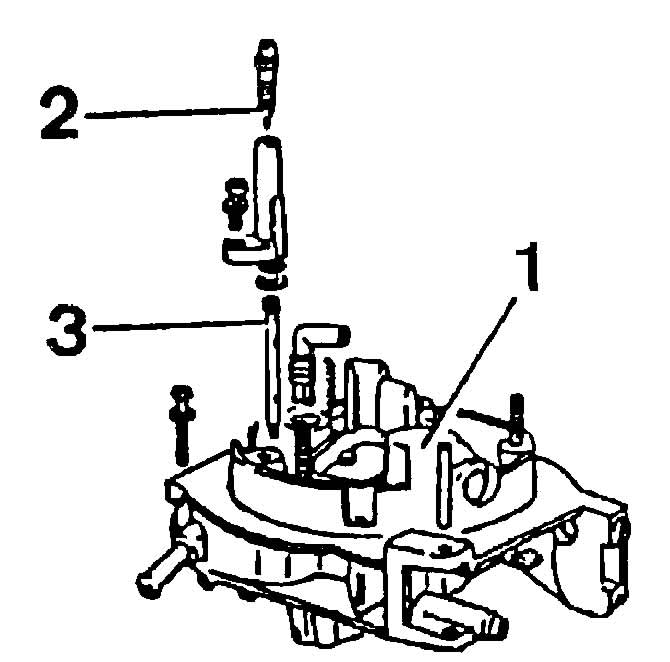
Pierburg 2E2 carburetor cover details:
1 - carburetor cover;
2 — adjusting screw for mixture quality (composition);
3 - emulsion tube.
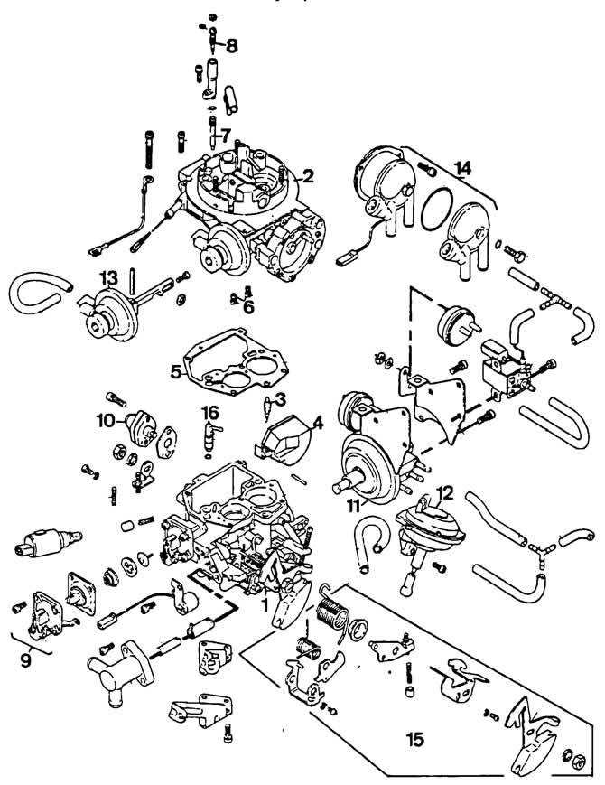
Plerburg 2E2 carburetor details:
1 - carburetor body;
2 - carburetor cover;
3 - needle valve;
4 - float;
5 - carburetor cover gasket;
6 - main fuel jets;
7 — idle fuel jet;
8 — adjusting screw for idle mixture quality (composition);
9 - accelerator pump;
10 — power mode economizer;
11 — pneumatic drive of the throttle valve of the 1st chamber;
12 — pneumatic drive of the throttle valve of the 2nd chamber;
13 — pneumatic drive of the air damper;
14 — automatic starting device housing;
15 — throttle control lever;
16 — accelerator pump nozzle.
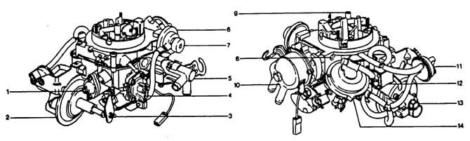
External appearance of the Pierburg 2E2 carburetor:
1 — power mode economizer;
2 — pneumatic drive of the throttle valve of the 1st chamber;
3 — stop screw of the throttle control lever of the 1st chamber;
4 - accelerator pump;
5 — housing of the thermal power element;
6 — pneumatic drive of the air damper;
7 — adjusting screw of the starting gap of the 1st stage of the air damper;
8 — adjusting screw of the starting gap of the 2nd stage of the air damper;
9 — mixture quality (composition) adjustment screw;
10 — Automatic starting device cover;
11 - pneumatic valve with thermal time relay;
12 - electromagnetic shut-off valve;
13 — adjusting screw for the output of the pneumatic drive rod of the 1st chamber throttle valve at forced idle;
14 — pneumatic drive of the throttle valve of the 2nd chamber.
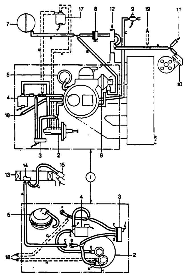
Vacuum hose connection diagram on the Pierburg 2E2 carburetor:
1 - carburetor;
2 — pneumatic drive of the throttle valve of the 1st chamber;
3 - pneumatic valve with thermal time relay;
4 - electromagnetic shut-off valve;
5 — pneumatic drive of the throttle valve of the 2nd chamber;
6 — pneumatic drive of the air damper;
7 — receiver;
8 - check valve;
9 - vacuum switch;
10 — vacuum regulator of ignition timing of the ignition distributor sensor;
11 - to the econometer;
12 - to the brake booster;
13 - air filter;
14 — thermopneumatic valve;
15 — pneumatic drive of the air intake flap;
16 — to the thermopneumatic valve;
17 — cold engine idle speed electromagnetic valve;
18 - to the cold engine idle speed solenoid valve;
19 - to the air conditioner.
The hoses marked with a dotted line are installed on cars with air conditioning. Wire color designation:
A - black;
B - light green;
C - colorless;
D — brown;
E - yellow;
F — blue;
G — white;
H - pink.
Starting device
Under the action of the thermostatic bimetallic spring of the automatic starting device, the air damper 1 (see diagrams) blocks the air supply to the carburetor duct. The throttle valve 2 of the 1st chamber is held in the slightly open position simultaneously by the three-nozzle pneumatic actuator 3, the rod 4 of which is retracted by the spring from the stop of the throttle valve of the 1st chamber, and the thermal power element 5 of the liquid heating system of the starting device, acting on the cam for opening the throttle valve of the 1st chamber. Due to the slightly opening of the throttle valve of the 1st chamber, a significant vacuum is created in the main metering system of the 1st chamber, which is necessary for starting a cold engine and increasing the crankshaft speed at idle (see diagram "A").
After starting the engine, the vacuum that occurs in the intake manifold acts on the pneumatic actuator 6 (see diagram "B"), which slightly opens the air damper. With the transition to the operating mode, the rods, driven by the throttle valve of the 1st chamber, open the air damper, as a result of which the fuel-air mixture becomes leaner and uninterrupted operation of the engine is ensured.
Idle and transition system
After the engine is started, the time relay thermal valve closes the connection between the pneumatic drive 3 of the throttle valve of the 1st chamber and the atmospheric air, and its rod returns to the position corresponding to the idle speed of the warmed-up engine. During engine warm-up, the throttle valve of the 1st chamber is held in a slightly open position due to the smooth heating of the thermal power element of the liquid heating system of the automatic starting device.
Fuel from the float chamber enters through the main fuel jet 7 into the emulsion tube well and the idle jet. Fuel mixes with air entering through the opening regulated by the screw 2 of the mixture quality (composition). The fuel-air mixture exits under the throttle valve through the slot 10 of the idle and transition system, which leads to a gradual increase in the engine crankshaft speed.
The transition system of the 2nd chamber operates in a similar manner, ensuring an increase in the crankshaft rotation frequency as the throttle valve of the 2nd chamber opens.
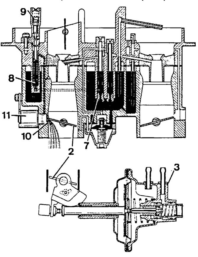
Diagram of the idle system and transition system of the 1st chamber of the Pierburg 2E2 carburetor:
2 - throttle valve of the 1st chamber;
3 — pneumatic drive of the throttle valve of the 1st chamber;
7 — main fuel jet of the 1st chamber;
8 — idle fuel jet;
9 — mixture quality (composition) adjustment screw;
10 — idle and transition system fuel-air mixture injection slot;
11 — pneumatic valve of the mixture heating system with a thermal time relay.
Main dosing system
Fuel through a needle valve, the flow area of which is regulated by a float, fills the float chamber and is held here at a constant level. The needle valve is connected to the float tongue by a hook.
From the float chamber, under the action of vacuum, the fuel enters the well of the emulsion tube through the main fuel jet 7 (see diagram) of the 1st chamber, where it mixes with the air coming out of the opening of the main air jet 12. The resulting emulsion is sprayed by the air flow passing through the small and large diffusers 13.
The main metering system of the 1st chamber includes a power mode economizer. When the vacuum in the area of the throttle valve 2 of the 1st chamber drops, caused by a significant opening of the throttle valve, there is no vacuum in the diaphragm cavity of the housing of the power mode economizer 14, the valve 15 of which, under the action of the spring, opens the channel 16 for supplying additional fuel to the fuel jet of the main metering system of the 1st chamber.
The main dosing system of the 2nd chamber operates similarly, in which an economizer is included instead of a power mode economizer. Enrichment of the fuel-air mixture in the full load mode in the 2nd chamber is ensured by spraying under the action of a strong vacuum of pure fuel through the injection tube 17 of the economizer, the outlet of which is located above the mixture formation zone.
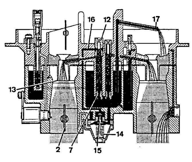
Diagram of the main metering systems of the Pierburg 2E2 carburetor:
2 - throttle valve 1st chamber;
7 — main fuel jet of the 1st chamber;
12 - main air jet of the 1st chamber;
13 — diffuser;
14 — housing of the pneumatic drive of the power mode economizer;
15 — economizer valve;
16 — fuel supply channel from the economizer;
17 — economizer injection tube.
Accelerator pump
When the throttle valve 2 (see diagram) of the 1st chamber is opened, the cam 18 actuates the lever 19 of the accelerator pump drive and the pump 20 pumps the fuel sucked from the float chamber into the mixture formation zone through the check valve and the sprayer 21.
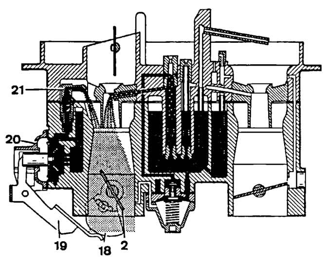
Accelerator pump diagram of the Pierburg 2E2 carburetor:
2 - throttle valve of the 1st chamber;
18 — accelerator pump drive cam;
19 — drive lever;
20 - accelerator pump;
21 - sprayer.
Visitor comments