
Starting device
When starting a cold engine under the influence of a thermostatic bimetallic spring of an automatic starting device, the air damper blocks the air flow through the carburetor duct, throttle valve 3 (see diagram) under the action of the system of rods and cams 2, the drive opens slightly, providing an increase in the rotational speed of a cold engine at idle.
Under the action of vacuum in the diaphragm cavity of the starting device, an increased amount of fuel passes through the main fuel jet, which ensures the start of a cold engine.
After starting the engine, the vacuum that occurs in the intake piping of the running engine drives the pneumatic actuator 4, which slightly opens the air damper. After warming up with the transition to the load mode through the system of rods and levers actuated by the throttle valve, the air damper opens slightly, which causes a depletion of the combustible mixture and ensures uninterrupted engine operation.
Idle system and transition system
Fuel taken from the float chamber through the main fuel jet 5 (see diagram) enters the well of the emulsion tubes and is supplied to the idle fuel jet 6. At the outlet of the jet 6, the fuel is mixed with air entering through the idle air jet. The emulsion is supplied to the outlet 7 of the idle system under the throttle valve through a hole regulated by a quality needle screw 8 (composition) mixture, and through the hole closed when the ignition is turned off by the electromagnetic shut-off valve 9.
When the throttle valve 3 is smoothly opened, the combustible mixture enters the vertical channel of the transition system 10, which leads to a gradual increase in the engine crankshaft speed.
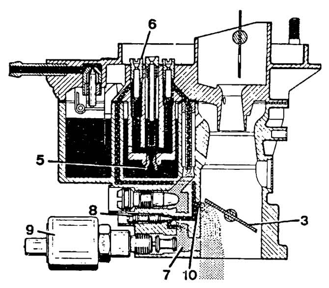
Scheme of the idle system and the transition system of the Pierburg 1VZ carburetor:
3 - throttle valve;
5 - main fuel jet;
6 - idle fuel jet;
7 - spray hole of the idle system;
8 - quality adjusting screw (composition) mixtures;
9 - electromagnetic shut-off valve;
10 - slots of the transition system.
Main dosing system
Fuel is fed through a needle valve into the float chamber. The float hinged on the axis regulates the opening of the needle valve opening to maintain a constant fuel level in the float chamber. There is a damping device between the needle valve and the float tongue.
From the float chamber fuel through the main fuel jet 5 (see diagram) enters the emulsion tube, where it mixes with the air flowing through the jet 11. Then the air-fuel mixture fills the mixing chamber formed by the small and large diffusers 12.
The carburetor has an econostat, which further enriches the air-fuel mixture at full engine load at speeds close to maximum. From the float chamber, the fuel passes through the channel and through the jet 13 enters the fuel tube, in the upper part of which it mixes with the air entering through the air jet 14. The resulting emulsion passes through the check valve 15 and is ejected through the injection tube 16 into the mixing chamber, further enriching combustible mixture, ensuring the operation of the engine at high speeds.
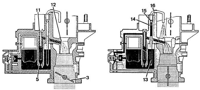
Scheme of the main dosing system and econostat of the Pierburg 1VZ carburetor:
3 - throttle valve;
5 - main fuel jet;
11 - main air jet;
12 - atomizer;
13 — fuel jet econostat;
14 — air jet econostat;
15 - check valve;
16 - injection tube
Accelerator pump
Under the action of the lever 17, the throttle valve opens, the spring 18 rotates the cam 19, which acts on the lever 20 of the accelerator pump drive. The lever presses on the piston 21, which pumps the fuel coming from the float chamber through the check ball valve 22 to the atomizer 23.
Cam drive spring 18 dampens the force of a sharp opening of the throttle, which increases the duration of fuel injection. The position of the cam drive spring on the throttle shaft is adjustable. The piston well has a sealing collar 24 and a return spring 25. The damper spring 26, located in the cavity of the piston itself, serves to regulate the movement of the piston depending on the amount of fuel passing through the atomizer.
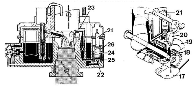
Pierburg 1VZ carburetor accelerator pump diagram:
17 - throttle control lever;
18 - accelerator pump cam drive spring;
19 - accelerator pump cam;
20 - accelerator pump drive lever;
21 - piston rod of the accelerating pump;
22 - check ball valve;
23 - spray accelerator pump;
24 - sealing cuff;
25 - return spring;
26 - damper spring of the accelerator pump piston.
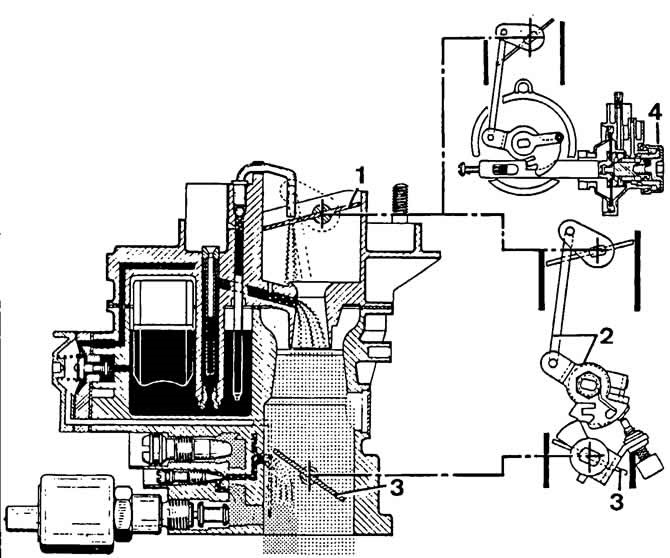
Scheme of operation of the Pierburg 1VZ carburetor when starting a cold engine:
1 - air damper;
2 - system of rods and cams for slightly opening the throttle;
3 - throttle valve;
4 - pneumatic actuator of the air damper.
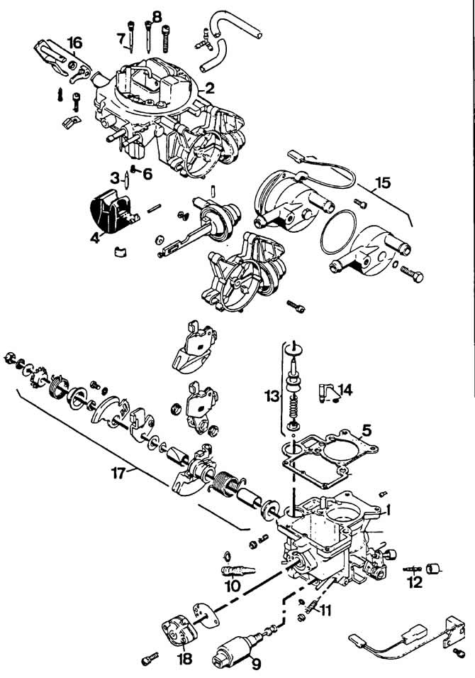
The main details of the Pierburg 1VZ carburetor:
1 - carburetor body;
2 - carburetor cover;
3 - needle valve;
4 - float;
5 - float chamber gasket;
6 - main fuel jet;
7 - idle fuel jet;
8 — fuel jet econostat;
9 - electromagnetic shut-off valve;
10 - adjusting screw for the amount of idle mixture;
11 - quality adjusting screw (composition) idle mixtures;
12 - restrictive screw throttle;
13 - accelerator pump;
14 - spray accelerator pump;
15 - automatic starting device;
16 - accelerator pump drive lever;
17 - levers and throttle control sectors;
18 - economizer power modes.
Visitor comments