



Contents: Device ↓ Operating principle ↓
Device
The electronic ignition system includes a distributor ignition sensor with a built-in contactless sensor (pulse generator sensor), commutator and high energy ignition coil.
Like the distributor of the contact ignition system, the sensor-distributor of the electronic ignition system has a centrifugal and vacuum ignition advance regulator. The contactless sensor assembled with a support plate and a toothed anchor has the ability to rotate depending on the vacuum supplied to the vacuum regulator.
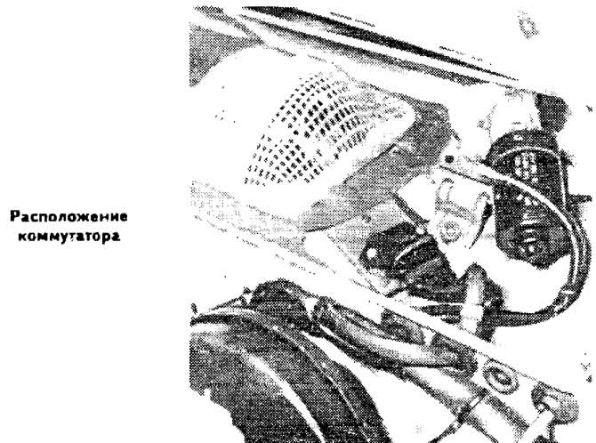
The switch is mounted on the outer upper front panel in the engine compartment to the mudguard of the right front wing on an aluminum base that provides cooling.
The switch converts pulses coming from the contactless sensor into control signals. The switch consists of a cascade for generating output signals from the contactless sensor (made in the form of a trigger), ignition timing control cascade, output amplification cascade, implemented according to the Darlington circuit and with a time delay.
The ignition coil, adapted to this ignition system, is installed next to the switch.
Operating principle
The magnetic part of the ignition distributor sensor, called the generator control pulse sensor, consists of the actual magnetic Hall sensor and a toothed anchor fixed to the rotor.
The magnetic flux in the ignition coil changes depending on the passage of the anchor teeth rotating in the interpolar gap of the magnetic sensor. When the anchor tooth enters the interpolar gap, the magnetic field in the integrated circuit of the Hall sensor is absent, and there is no induced current. When the anchor tooth leaves the interpolar gap, in accordance with the law of induction, an alternating voltage arises in the Hall sensor circuit, the circuit closes and a control pulse is formed.
The width of the anchor teeth corresponds to the angle of the cam.
The switch controls the ignition depending on the rotation speed of the ignition distributor shaft, the battery voltage, the total resistance of the ignition coil, and in any engine operating mode it produces constant voltage pulses.
Interruption of the current in the primary winding of the ignition coil by the commutator causes a sharp change in the magnetic flux in the coil and the appearance of a high voltage current in the secondary winding of the ignition coil.
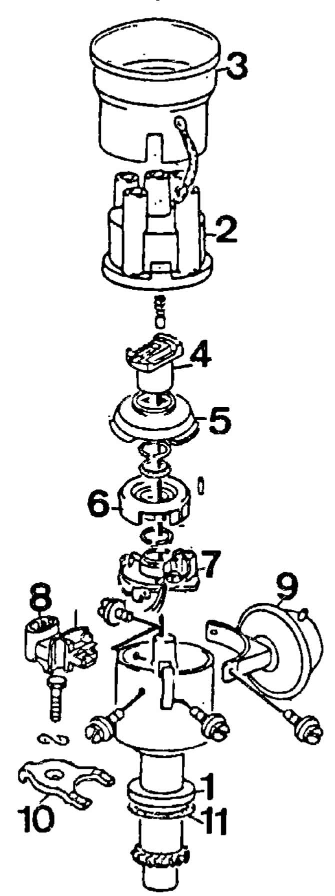
Distributor sensor details:
1 — distributor sensor housing;
2 - lid;
3 - interference suppression screen;
4 — distributor rotor;
5 - protective screen;
6 - toothed screen;
7 - generator sensor of control pulses;
8 — connector;
9 - vacuum regulator;
10 — flange of the sensor-distributor housing;
11 — gasket.
Visitor comments